Optical coherence tomography method and optical coherence tomography apparatus

一种光学相干层析、摄影装置的技术,应用在采用光学装置、测量装置、医药科学等方向,能够解决横向分辨率变低等问题

Inactive Publication Date: 2010-09-08
CANON KK
View PDF4 Cites 2 Cited by
  • Summary
  • Abstract
  • Description
  • Claims
  • Application Information

AI Technical Summary

Problems solved by technology

On the other hand, if the numerical aperture is reduced, then the depth of focus becomes larger, but the lateral resolution becomes lower

Method used


Image

  • Optical coherence tomography method and optical coherence tomography apparatus
  • Optical coherence tomography method and optical coherence tomography apparatus
  • Optical coherence tomography method and optical coherence tomography apparatus

Examples


Embodiment Construction

[0026] Hereinafter, an optical coherence tomography apparatus according to the present embodiment will be described.

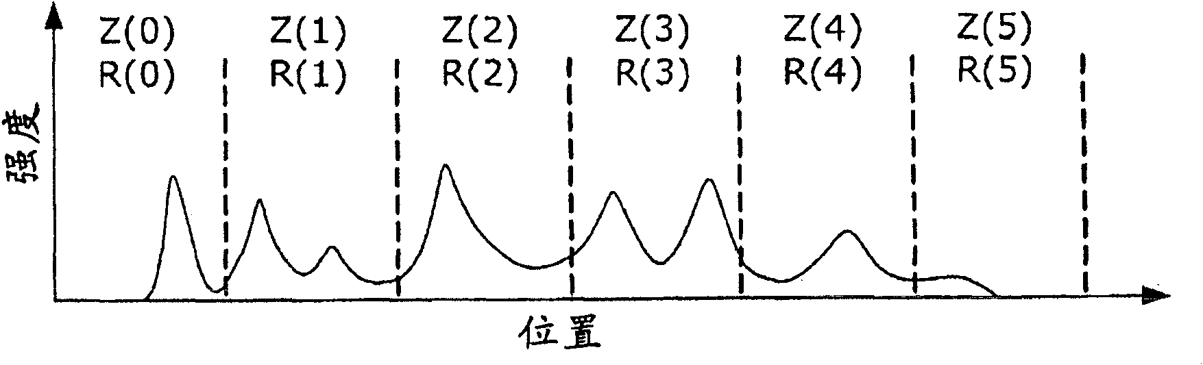
[0027] The optical coherence tomography apparatus according to the present embodiment separates light from a light source into measurement light and reference light through a divided optical path. The measuring light is irradiated onto the object to be measured through the measuring optical path. The return light returned from the object to be measured when the measurement light is irradiated is guided to the detection position through the detection optical path. The focus position of the measurement light (in the irradiation direction) in the object to be measured can be controlled by a focus drive mechanism. The reference light is guided to the detection position through the reference light path. In the reference light path, a mirror is set, and the position of the coherence gate can be adjusted through a mirror driving mechanism. Since the coherence gate...


PUM


Abstract

An optical coherence tomography method according to the present invention comprising the steps of dividing an object to be measured into a plurality of measurement regions adjacent to one another in a direction of irradiation of a measurement light, and acquiring a measurement image for every measurement region based on a wavelength spectrum of a coherent light and acquiring a tomographic image for every measurement region by removing a mirror image of a tomographic image of an adjacent region being adjacent to the measurement region of the measurement image from the measurement image.

Description

technical field [0001] The present invention relates to an optical coherence tomography method and an optical coherence tomography apparatus, and more particularly, to an optical coherence tomography method and an optical coherence tomography apparatus using a coherence optical system used in the medical field. Background technique [0002] Currently, there are various ophthalmic devices using optical devices. Examples of such ophthalmic devices include anterior eye imaging devices, retinal cameras, and scanning laser ophthalmoscopes (SLOs). Among these ophthalmic devices, an optical coherence tomography (OCT) apparatus is capable of obtaining tomographic images of a subject to be measured at high resolution, and thus is becoming an indispensable device for outpatient medical treatment in retinal specialties. [0003] For example, an OCT apparatus is disclosed in Japanese Patent Application Laid-Open No. H11-325849. In the OCT device disclosed in Japanese Patent Applicatio...

Claims


Application Information

Patent Timeline
Patent Type & Authority Applications(China)
IPC IPC(8): A61B3/14
CPCG01B9/02078A61B3/102G01B9/02091G01B9/02085G01B9/02063G01B9/02044
Inventor 末平信人
Owner CANON KK
Why Eureka
Try Eureka