Device for setting operation clearance on spinning room preparation machine

A technology of working gap and preparation machine, applied in textile and papermaking, deburring device, fiber processing, etc., can solve the problems of attachment and installation workload, warpage, etc., and achieve the effect of saving space and high functionality

Active Publication Date: 2010-09-08
TRUETZSCHLER GRP SE
View PDF8 Cites 6 Cited by
  • Summary
  • Abstract
  • Description
  • Claims
  • Application Information

AI Technical Summary

Problems solved by technology

Disadvantages are: With unequal radial settings, undesired warpage occurs, moreover, the geometry depends on the number of set mandrels, i.e. the accuracy of the distance between the top card and the cylinder wire and uniformity are not the same at all locations along the entire curved track
Another disadvantage is the need for additional space
Another problem is the amount of installation work necessary to attach the set curves

Method used


Image

  • Device for setting operation clearance on spinning room preparation machine
  • Device for setting operation clearance on spinning room preparation machine
  • Device for setting operation clearance on spinning room preparation machine

Examples


Embodiment Construction

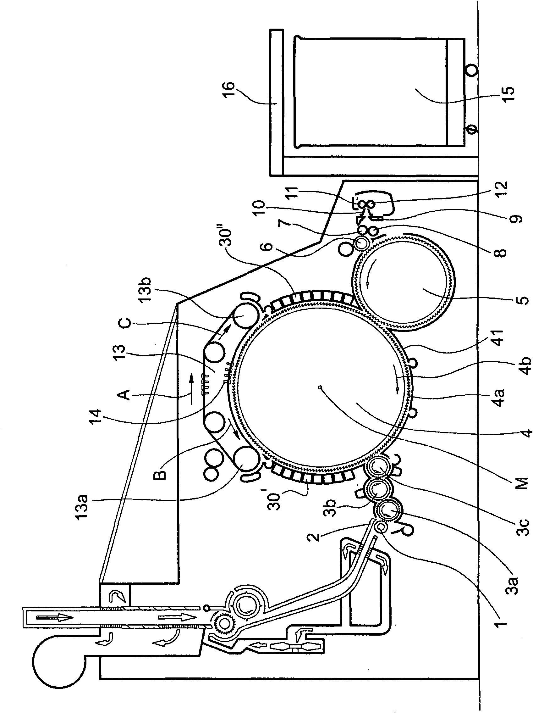
[0031] figure 1 A card (for example a Trützschler TC 07 flat card) is shown comprising a feed roller 1, a feed plate 2, licker-in rollers 3a, 3b, 3c, a cylinder 4, a doffer 5, a stripping roller 6, Rollers 7, 8, web guide elements 9, web bell mouth 10, transfer rollers 11, 12, revolving top card 13 with top card strip guide rollers 13a, 13b and top card strip 14, can 15 and Coiler 16. The direction of rotation of the rollers is indicated by the curved arrows. The letter mark M represents the center point (axis) of the cylinder 4 . The numeral 4a indicates the clothing and the numeral 4b indicates the direction of rotation of the cylinder 4 . The letter B indicates the direction of rotation of the revolving top carding element 13 in the carding position, while the letter C indicates the return conveying direction of the top carding strip 14, and the numeral 30 I 、30 IIDesignates functional components and numeral 41 designates the cover below the cylinder 4 . Arrow A indic...


PUM


Abstract

The present invention relates to a device for setting working nip on a spinning room preparation machine, particularly a flat card, a roller card, etc. The device is provided with a roller, such as a cylinder which has a cylindrical clothed wall surface, and to have, located opposite the roller clothing and spaced apart radially therefrom, clothed and / or non-clothed movable or fixed machine elements and two fixed lateral holding devices (side screens), in which setting bends are provided as supporting elements for the machine elements, which setting bends are associated with the lateral holding devices, the setting bends being used for setting the working nip and positioning devices being associated with the setting bends, wherein the latera] holding device and at least one associated setting bend are in the form of a one-piece component and the setting bend is divided into individual separate sections, the component having between holding device and setting bend through-openings in or between which flexible positioning elements for the setting bend are arranged.

Description

technical field [0001] The invention relates to devices for setting the working gap on spinning room preparation machines, in particular flat cards, roller cards, etc., with rollers such as cylinders with cylindrical clothing-covered wall surfaces , and has movable or stationary machine elements, clothed and / or unwired, opposite and radially spaced apart from the roller wires, and two fixed lateral holding devices (side screens), where There is a set curved track as the support element of the machine element, the set curved track is connected with the horizontal holding device (side screen), the set curved track is used to set the working gap, and the positioning device is connected with the set curved track rail connection. Background technique [0002] In modern cards it is important to set the carding gap, ie the distance between the cylinder clothing and the clothing and working elements located opposite it, before the machine is started up. This setting work is necess...

Claims


Application Information

Patent Timeline
Patent Type & Authority Applications(China)
IPC IPC(8): D01G15/28
CPCD01G15/30
Inventor A·莱德
Owner TRUETZSCHLER GRP SE
Why Eureka
Try Eureka