Lighting equipment

A technology of lighting fixtures and semiconductors, applied in lighting devices, lighting auxiliary devices, fixed lighting devices, etc., can solve the problems of reduced light extraction efficiency and achieve the effect of improving light extraction efficiency

Inactive Publication Date: 2010-09-08
TOSHIBA LIGHTING & TECH CORP +1
View PDF7 Cites 1 Cited by
  • Summary
  • Abstract
  • Description
  • Claims
  • Application Information

AI Technical Summary

Problems solved by technology

[0005] However, when a baffle is used to prevent glare, if the edge of the opening on the upper surface of the baffle is located near the exit opening of the reflector, part of the light emitted from the exit opening of the reflector will be blocked. The edge of the opening on the upper surface of the board is covered, so there is a problem that the light extraction efficiency (light extraction efficiency) will decrease when the light of the LED is extracted to the outside.
In particular, the direct light from the LED is blocked by the baffle, which tends to reduce the light extraction efficiency

Method used


Image

  • Lighting equipment
  • Lighting equipment
  • Lighting equipment

Examples


Embodiment Construction

[0049] Hereinafter, an embodiment of the present invention will be described with reference to the drawings.

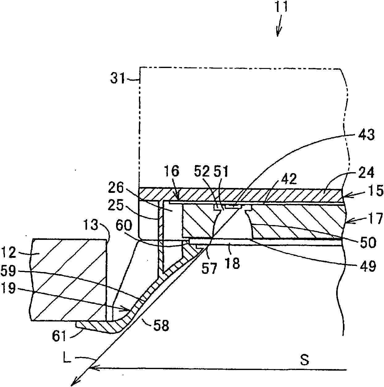
[0050] Such as figure 1 As shown, the lighting fixture 11 is, for example, a downlight, and is embedded in a circular embedding hole 13 provided in a ceiling member 12 such as a ceiling.

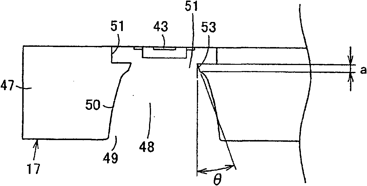
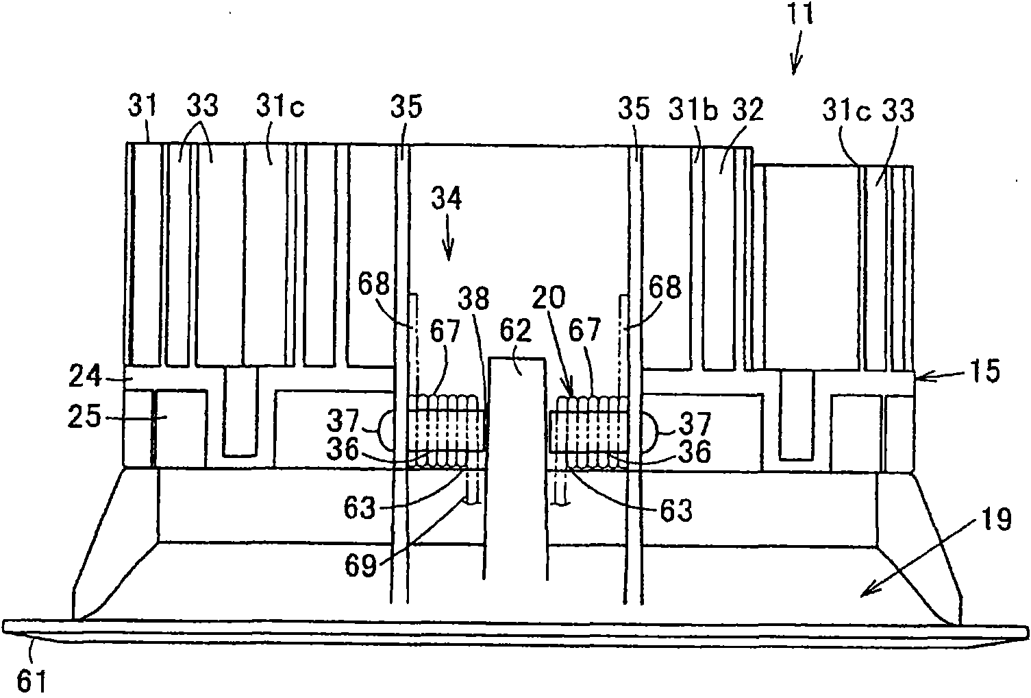
[0051] Such as Figure 1 to Figure 6As shown, the lighting fixture 11 includes a fixture body 15, a light source module (module) 16 installed on the lower surface of the fixture body 15, a reflector 17 as a first reflector installed on the lower side of the light source module 16, and configured on The translucent cover 18 on the lower surface of the reflector 17, the baffle plate 19 as the second reflector attached to the underside of the appliance body 15, and a pair of mounting springs for attaching to the top plate member 12 20 and a power supply device and a terminal block not shown in the figure, wherein the installation spring 20 is installed on the outer surface of the ap...


PUM


Abstract

LEDs (43), a reflector (17), and a baffle (19) are disposed on the underside of the equipment main body (15). An emission opening (49) for emitting light of the LEDs (43) and a reflection surface (50) for emitting light of the LEDs from the emission opening by reflecting the same are provided in the reflector. The baffle (19) is disposed outside the direct light emission area where direct light from the LEDs is emitted from the emission opening of the reflector. The direct light from the LEDs (43) can be picked up without being blocked by the upper end of the baffle (19), and the light pick-up efficiency can be improved.

Description

technical field [0001] The invention relates to a lighting fixture using a semiconductor light emitting element as a light source. Background technique [0002] Conventionally, there have been lighting fixtures such as down-lights using light-emitting diodes (LEDs) as semiconductor light-emitting elements. In this lighting fixture, a substrate on which a plurality of LEDs are mounted is disposed on the fixture body, a reflector for controlling light distribution of light from the LEDs is disposed on the underside of the substrate, and a reflector is disposed on the lower surface of the reflector. The light-transmitting cover is further provided with a decorative frame on the lower part of the appliance body, and the decorative frame supports the light-transmitting cover and is abutted against and mounted on the top plate. [0003] The lower surface of the reflector has an exit opening for emitting light from the LED, and a reflective surface extending toward the exit openin...

Claims


Application Information

Patent Timeline
Patent Type & Authority Applications(China)
IPC IPC(8): F21S2/00F21V7/10F21V17/00
CPCF21V29/2225F21V29/2243F21V15/011F21V21/04F21V7/09F21V29/2262F21V7/0025F21V21/046F21V7/0083F21S8/02F21Y2101/02F21V29/507F21V29/75F21V29/76F21V29/77F21Y2115/10
Inventor 樋口一斎森山厳与桥本纯男渡边智仓持裕行
Owner TOSHIBA LIGHTING & TECH CORP
Why Eureka
Try Eureka