Failure detecting equipment of power communication transmission channel, failure detecting system and method

A fault detection and transmission channel technology, applied in the field of communication, can solve the problems of unable to provide channels, unable to replace the communication synchronous transmission system, less types of channel faults, etc., to achieve the effect of real-time detection

Active Publication Date: 2010-09-08
NORTH CHINA ELECTRICAL POWER RES INST +2
0 Cites 24 Cited by

AI-Extracted Technical Summary

Problems solved by technology

[0003] However, with the extensive use of longitudinal current differential protection, there are more and more incorrect phenomena such as protection device alarms caused by abnormal conditions in digital channels. Existing equipment cannot test the performance of protection equipment well, such as TWM-1 Communication Error Code Generator, the disadvantages ...

Method used

[0056] Beneficial technical effects of the present invention: by adding an analog signal to the data transmitted in the transmission c...

Abstract

The invention provides failure detecting equipment of a power communication transmission channel, a failure detecting system and a method. The equipment is characterized by comprising a transmitting end synchronous digital transmission device, an interference signal generating device and a receiving end synchronous digital transmission device, wherein the transmitting end synchronous digital transmission device is used for receiving state data transmitted by transmitting end protecting equipment and transmitting the state data into an optical fiber for transmission; the interference signal generating device is used for adding an interference signal into the state data; and the receiving end synchronous digital transmission device is used for receiving the state data transmitted from the optical fiber and transmitting the state data to receiving end protecting equipment for carrying out detecting processing. The embodiment of the invention adds simulating interference into the inward transmitted data of the transmission channel and can detect the performance of a relay protecting device in real time and execute alarm operation in time.

Application Domain

Technology Topic

Data transmissionFiber optic transmission +5

Image

  • Failure detecting equipment of power communication transmission channel, failure detecting system and method
  • Failure detecting equipment of power communication transmission channel, failure detecting system and method
  • Failure detecting equipment of power communication transmission channel, failure detecting system and method

Examples

  • Experimental program(1)

Example Embodiment

[0024] The following will clearly and completely describe the technical solutions in the embodiments of the present invention with reference to the accompanying drawings in the embodiments of the present invention. Obviously, the described embodiments are only some, not all, embodiments of the present invention. Based on the embodiments of the present invention, all other embodiments obtained by persons of ordinary skill in the art without making creative efforts belong to the protection scope of the present invention.
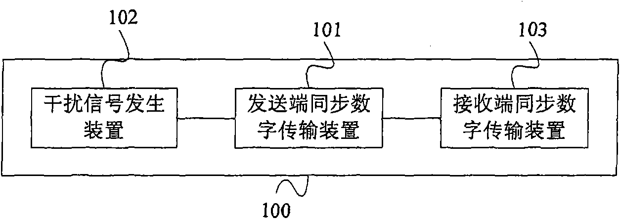
[0025] figure 1 It is the structure of the power communication transmission channel fault detection equipment according to the embodiment of the present invention Figure 1. like figure 1 As shown, the power communication transmission channel fault detection device 100 includes: a synchronous digital transmission device 101 at the sending end, which is used to receive the status data sent by the protection device at the sending end, and transmit the status data into the optical fiber for transmission; interference The signal generating device 102 is used to add an interference signal to the status data; the receiving end synchronous digital transmission device 103 is used to receive the status data transmitted from the optical fiber, and transmit the status data to the receiving end protection device Perform detection processing.
[0026] like figure 2 As shown, the power communication transmission channel fault detection device 200 further includes a sending-end pulse code modulation device 201 and a receiving-end pulse code modulation device 202 . The pulse code modulation device 201 at the sending end is used to provide a route with a bandwidth of 64K, receive the status data sent by the protection device at the sending end, and send the status data to the synchronous digital transmission device 101 at the sending end; The encoding and modulating device 202 is configured to provide a route with a bandwidth of 64K, receive the status data sent by the synchronous digital transmission device at the receiving end, and send the status data to the protection device at the receiving end for detection and processing. The interference signal generating means 102 is used for adding an interference signal before the transmitting end pulse code modulation means 201 or for adding an interference signal after the transmitting end pulse code modulation means 201 . figure 2 The middle is to add an interference signal after the pulse code modulation device 201 at the transmitting end, image 3 The structure of the power communication transmission channel fault detection device 300 according to the embodiment of the present invention Figure three , adding an interference signal before the pulse code modulation device 201 at the transmitting end.
[0027] Figure 4 It is a flowchart of a method for detecting a fault in a power communication transmission channel according to an embodiment of the present invention. like Figure 4 As shown, the method includes:
[0028] Step S401: Send the status data sent by the protection device at the sending end and the status data added with the interference signal to the synchronous digital transmission device at the sending end;
[0029] Step S402: receiving the state data, and transmitting the state data to the synchronous digital transmission device at the receiving end through an optical fiber;
[0030] Step S403: Receive the state data transmitted from the optical fiber, and transmit the state data to the protection device at the receiving end for detection processing.
[0031] Figure 5 It is a structural diagram of a fault detection system 500 according to an embodiment of the present invention. The fault detection system includes a transmitting end protection device 501, a power communication transmission channel fault detection device 502 and a receiving end protection device 503, wherein the transmitting end protection device 501 is used to send The power communication transmission channel fault detection device sends status data; the power communication transmission channel fault detection device 502 is used to receive the status data, add an interference signal to the status data, and transmit the status data; the receiving end protection device 503 is used to receive the state data sent by the power communication transmission channel fault detection device, calculate the bit error rate, compare the bit error rate with a fixed value, and execute an alarm if the bit error rate is greater than the fixed value operate.
[0032] Image 6 The flow chart of the fault detection method in the embodiment of the present invention, the fault detection method includes:
[0033] Step 601: Send status data to the power communication transmission channel fault detection device;
[0034] Step 602: The power communication transmission channel fault detection device adds an interference signal to the state data, and transmits the state data;
[0035] Step 603: Receive the status data sent by the power communication transmission channel fault detection device, calculate the bit error rate, compare the bit error rate with a fixed value, and execute an alarm if the bit error rate is greater than the fixed value operate.
[0036] In the embodiment of the present invention, the synchronous digital transmission device at the sending end and the synchronous digital transmission device at the receiving end are synchronous digital transmission equipment (SDH equipment), such as XJ CGCS-1000 SDH equipment; the pulse code modulation device at the sending end and the receiving end The pulse code modulation device is pulse code modulation (PCM) equipment, and the PCM equipment can be, for example, Nokia PCM equipment, Sagem PCM equipment, and XJ PCM equipment; the sending end protection equipment and the receiving end protection equipment are relay protection devices, for example, they can be For RCS931 longitudinal differential protection equipment and CSC103 longitudinal differential protection equipment, the status data sent by the protective device at the sending end is the operating status data or alarm data of the protective device at the sending end.
[0037]The relay protection device, channel switching device, PCM equipment and SDH equipment constitute the synchronous transmission system of double-terminal power communication in the laboratory. The SDH equipment can provide 2M routing during the transmission process, such as Figure 7 As shown, it is a schematic diagram of transmission of status data between the SDH equipment at the transmitting end and the SDH equipment at the receiving end during the transmission process of the SDH equipment according to the embodiment of the present invention. The laboratory double-terminal power communication synchronous transmission system can be divided into multiple SDH transmission channels. If the signal transmission flow in the laboratory double-terminal power communication synchronous transmission system is 2nM, then 2n pairs of sending end SDH equipment and receiving end SDH can be connected equipment. Optical signals are transmitted between the SDH equipment at the sending end and the SDH equipment at the receiving end through optical fibers. The signal is converted into an optical signal, and then the optical signal is converted into an electrical signal, which is transmitted to the SDH equipment at the receiving end through an optical fiber. The SDH equipment at the receiving end receives the optical signal and converts the optical signal into an electrical signal through the photoelectric conversion device 704 of the SDH equipment at the receiving end. , and then transmitted to the relay protection device 705 at the receiving end.
[0038] PCM equipment can provide 64K routing, so an SDH transmission channel can be divided into (2×1024/64)=32 pairs of PCM equipment, such as Figure 8 As shown, one SDH transmission channel can connect 32 PCM devices 801 at the sending end before the SDH device at the sending end, and can connect 32 PCM devices 802 at the receiving end after the SDH device at the receiving end.
[0039] The signal generating device can be, for example, a code error generator or a channel detection device, the code error generator can be a TWM-1 communication code error generator, and the channel detection device can be a Datang Telecom channel detection platform. TWM-1 communication bit error generator is mainly used to generate bit errors; Datang Telecom channel detection platform can generate various interferences such as channel switching, channel delay change, bit error, interruption, frame loss alarm, self-loop, clock frequency change, etc. Signal.
[0040] When there is no PCM equipment in the power communication transmission channel fault detection equipment, the performance of the relay protection devices at both ends is measured by using the transmission channel composed of the SDH equipment at the transmitting end, the SDH equipment at the receiving end and the signal generating device. The following takes the TWM-1 communication bit error generator as an example to illustrate how to test the performance of the relay protection devices at both ends.
[0041] The performance of the relay protection device refers to its ability to withstand the interference signal added to the signal transmitted in the channel. The relay protection device at the sending end immediately generates a status signal reflecting its operating status or alarm, and the status signal is processed to generate a digital signal, such as 01101100, and correspondingly generates a check code for the digital signal. Each digital signal corresponds to a unique calibration code. Check code, for example, the check code of the digital signal 01101100 is set to ABCDEF. The relay protection device at the sending end sends real-time digital signals and their corresponding check codes to the SDH equipment at the sending end at intervals, assuming that the time interval is 5ms, such as Figure 9 As shown, a digital signal is generated every 5ms, and a corresponding check code is generated.
[0042] The status signal generated by the relay protection device at the sending end is converted into a digital signal every 5ms, and a check code corresponding to the digital signal is generated, and the digital signal is processed into a data packet. For example, the relay protection device at the sending end converts the alarm signal in the state signal at a certain moment into a digital signal 00110101, generates a check code BADCFE, packs 00110101 and BADCFE into data packet 1 (00110101, BADCFE), which is the alarm data, and then Data packet 1 (00110101, BADCFE) is transmitted to the SDH equipment 802 at the sending end.
[0043] The data transfer process is as Figure 10 As shown, the data packet 1 (00110101, BADCFE) sent from the relay protection device 1001 at the transmitting end is transmitted in the form of an optical signal, and there is an optical-electrical interface ( not shown in the figure), is used to use the photoelectric conversion device to convert the optical signal transmitted from the optical fiber by the relay protection device 1001 at the sending end into an electrical signal at the photoelectric interface, and then send the data packet to the SDH equipment 1002 at the sending end through a coaxial cable 1 (00110101, BADCFE), during the SDH transmission process of data packet 1 (00110101, BADCFE) to the sending end, the TWM-1 communication bit error generator 1003 adds an interference signal to data packet 1 (00110101, BADCFE), and data packet 1 (00110101, BADCFE) becomes packet 1 (00110100, BADCFE). The SDH equipment 1002 at the sending end converts the data packet 1 (00110100, BADCFE) added with the interference signal from the form of an electrical signal to an optical signal through an optical-to-electrical conversion interface, and transmits it to the SDH equipment 1004 at the receiving end through an optical fiber. After receiving the data packet 1 (00110100, BADCFE), the SDH equipment at the receiving end converts the form of an optical signal into an electrical signal through the photoelectric conversion interface, and sends it to the relay protection device 1005 at the receiving end. There is also a photoelectric interface (not shown in the figure) between the relay protection device at the receiving end and the SDH equipment 1004 at the receiving end, which is used to transfer the electrical data transmitted by the SDH equipment 1004 at the receiving end from the coaxial cable through the photoelectric conversion device. The signal is converted into an optical signal, and then 1 (00110100, BADCFE) is transmitted to the relay protection device 1005 at the receiving end through an optical fiber for detection.
[0044] The relay protection device 1005 at the receiving end and the relay protection device 1001 at the sending end have a mapping relationship table, such as Figure 11 As shown, the same digital signal corresponds to a unique check code, and only part of the corresponding relationship between the check code and the digital signal is shown in the figure.
[0045] like Figure 12 As shown, the relay protection device 1005 at the receiving end includes a calculation module 1201 (calculation device) and a detection processing module 1202 (detection processing device), and the calculation module 1201 is used to Figure 11 In the mapping relationship between the digital signal and the check code, compare whether the digital signal and the check code in the received data packet 1 are in the mapping table, the specific method is as follows:
[0046] Check the check code BADCFE in packet 1 (00110100, BADCFE) in Figure 11 The corresponding digital signal in is 11001101, and the digital signal in data packet 1 is 00110100. It can be known that interference signals are added to data packet 1 by the TWM-1 communication bit error generator, and the calculation module 1201 compares the data transmitted every 5ms Packages are tested in the same way. The TWM-1 communication code error generator only adds interference signals to some data, and the TWM-1 communication code error generator can be set to add interference signals at regular intervals, for example, it can be set to add interference signals every 40ms. The calculation module 1201 detects whether the digital signal in each data packet is changed to a bit error by an interference signal, and calculates the number of data packets that are changed to a bit error by adding an interference signal in 100 consecutive data packets, assuming that there are 8 data packets calculated The packet is changed to a bit error by the interference signal, and 92 data packets are not changed to a bit error by the interference signal, and the bit error rate is 8%. The detection processing module 1202 compares 8% with the allowable bit error rate of the relay protection device, if The allowable bit error rate of the relay protection device is 7% (different relay protection devices have different bit error rates), which means that the relay protection device cannot withstand a bit error rate of 8%, and the detection processing module 1202 will perform an alarm operation. If the bit error rate of the relay protection device is 10%, it means that the relay protection device can withstand a bit error rate of 8%, and the detection processing module 1202 does not perform an alarm operation.
[0047] The above describes how to detect the transmission performance of the relay protection equipment when there is no PCM equipment. When there is PCM equipment, the data transmission is similar to that without PCM equipment. The difference is that when the sending end PCM equipment is connected before the sending end SDH equipment, The interference signal can be added before the PCM device at the sending end, or added after the PCM device at the sending end.
[0048] The data transfer process is as Figure 13 As shown, the PCM device 1301 at the sending end is added before the SDH device at the sending end, and the PCM device 1302 at the receiving end is added after the SDH device at the receiving end. Take the TWM-1 communication error generator before the SDH device at the sending end to generate interference signals as an example Be explained.
[0049] like Figure 13 As shown, the data packet 1 (00110101, BADCFE) sent from the relay protection device 1001 at the sending end is transmitted in the form of an optical signal, and there is a photoelectric interface between the relay protection device at the sending end and the PCM device at the sending end (in the figure not shown), is used to use the photoelectric conversion device to convert the optical signal transmitted by the optical fiber transmission of the transmitting end relay protection device 1001 into an electrical signal at the optical interface, and then transmit it to the transmitting end PCM device 1301 through a shielded twisted pair, and the transmitting end The PCM device 1301 receives the data packet 1 (00110101, BADCFE), and transmits it to the sending end SDH. During the SDH transmission process of data packet 1 (00110101, BADCFE) to the transmitting end, the TWM-1 communication bit error generator 1003 adds an interference signal to data packet 1 (00110101, BADCFE), and data packet 1 (00110101, BADCFE) becomes Packet 1 (00110100, BADCFE). The SDH equipment 1002 at the sending end converts the data packet 1 (00110100, BADCFE) added with the interference signal from the form of an electrical signal to an optical signal through an optical-to-electrical conversion interface, and transmits it to the SDH equipment 1004 at the receiving end through an optical fiber. After receiving the data packet 1 (00110100, BADCFE), the SDH device 1004 at the receiving end converts the form of the optical signal into the form of an electrical signal through the photoelectric conversion interface, and then transmits it to the PCM device 1302 at the receiving end, and the PCM device 1302 at the receiving end transmits and receives After data packet 1 (00110100, BADCFE), it is sent to the relay protection device 1005 at the receiving end. There is also a photoelectric interface (not shown in the figure) between the relay protection device 1005 at the receiving end and the PCM device 1302 at the receiving end, which is used to transmit the PCM device 1302 at the receiving end from the shielded twisted pair to the photoelectric interface using a photoelectric conversion device. The electrical signal is converted into an optical signal, and then the data packet 1 (00110100, BADCFE) is transmitted to the relay protection device 1005 at the receiving end through an optical fiber.
[0050] The relay protection device 1005 at the receiving end and the relay protection device 1001 at the sending end have a mapping relationship table, such as Figure 11 As shown, the same digital signal corresponds to a unique check code, and only part of the corresponding relationship between the check code and the digital signal is shown in the figure.
[0051] like Figure 12 As shown, the relay protection device 1005 at the receiving end includes a calculation module 1001 and a detection processing module 1202, and the calculation module 1201 is used to Figure 11 In the mapping relationship between the digital signal and the check code, compare whether the digital signal and the check code in the received data packet 1 are in the mapping table, the specific method is as follows:
[0052] Check the check code BADCFE in packet 1 (00110100, BADCFE) in Figure 11The corresponding digital signal in is 11001101, and the digital signal in data packet 1 is 00110100. It can be known that interference signals are added to data packet 1 by the TWM-1 communication bit error generator, and the calculation module 1201 compares the data transmitted every 5ms Packages are tested in the same way. The TWM-1 communication code error generator only adds interference signals to some data, and the TWM-1 communication code error generator can be set to add interference signals at regular intervals, for example, it can be set to add interference signals every 40ms. The calculation module 1201 detects whether the digital signal in each data packet is changed into a bit error by the interference signal, and calculates the number of data packets added with the interference signal in 100 consecutive data packets, assuming that 8 data packets are calculated by the interference signal 92 data packets are not changed into errors by interference signals, and the error rate is 8%. The detection processing module 1202 compares 8% with the allowable bit error rate of the relay protection device. If the relay protection device If the allowable bit error rate is 7%, it means that the relay protection device cannot withstand a bit error rate of 8%, and the detection processing module 1202 will perform an alarm operation. If the bit error rate of the relay protection device is 10%, it means that the relay protection device can withstand a bit error rate of 8%, and the detection processing module 1202 does not perform an alarm operation.
[0053] The communication transmission channel between the relay protection device at the sending end and the relay protection device at the receiving end is a two-way channel, and the receiving end and the sending end are mutual. When the communication is initiated from the relay protection device at the receiving end, the relay protection device at the receiving end acts as the relay protection device at the sending end, performing the function of the relay protection device at the sending end, and the relay protection device at the sending end performs the functions of the receiving relay protection device Function. Similarly, the SDH device at the receiving end can also be used as the SDH device at the sending end, and the PCM device at the receiving end can also be used as the PCM device at the sending end. For example, Figure 14 shown (PCM device not shown).
[0054] In the embodiment of the present invention, only TWM-1 communication bit error generator generates bit errors to change the data transmitted in the channel, and the Datang Telecom channel detection platform can also add interference signals to the transmitted data to change the original data, for example, it can generate Various interference signals such as channel switching, channel delay change, bit error, interruption, frame loss alarm, self-loop, clock frequency change, etc. The purpose of these interference signals is to change the transmitted data, so I will not repeat them here.
[0055] The relay protection device in the embodiment of the present invention can be a protection device produced by different manufacturers, such as RCS931 longitudinal differential protection equipment and CSC103 longitudinal differential protection equipment. Different relay protection devices bear different bit error rates. A relay protection device has a fixed value of the bit error rate. Once the bit error rate transmitted in the channel is higher than the fixed value of the device's bit error rate, the relay protection device will perform an alarm operation, which can effectively detect the relay protection. performance of the device.
[0056] Beneficial technical effects of the present invention: by adding analog signals to the data transmitted in the transmission channel, the performance of the relay protection device can be detected in real time, and the alarm operation can be performed in time.

PUM

no PUM

Description & Claims & Application Information

We can also present the details of the Description, Claims and Application information to help users get a comprehensive understanding of the technical details of the patent, such as background art, summary of invention, brief description of drawings, description of embodiments, and other original content. On the other hand, users can also determine the specific scope of protection of the technology through the list of claims; as well as understand the changes in the life cycle of the technology with the presentation of the patent timeline. Login to view more.

Similar technology patents

Classification and recommendation of technical efficacy words

Why Eureka
Try Eureka