Synchronization error correction method
A technology of synchronization error and synchronization source, applied in synchronization devices, digital transmission systems, electrical components, etc., can solve problems such as difficult discrete devices, and achieve the effects of wide application, high synchronization control reliability, and low implementation cost.
Inactive Publication Date: 2010-09-08
陈秋玲
View PDF6 Cites 15 Cited by
- Summary
- Abstract
- Description
- Claims
- Application Information
AI Technical Summary
Problems solved by technology
The above three synchronization error calibration methods are basically based on the estimation of the transmission delay and compensation based on the estimation. None of them belong to the learning synchronization error correction that uses the self-learning method to
Method used
View moreImage
Smart ImageViewing Examples

Examples
 PUM
 Abstract
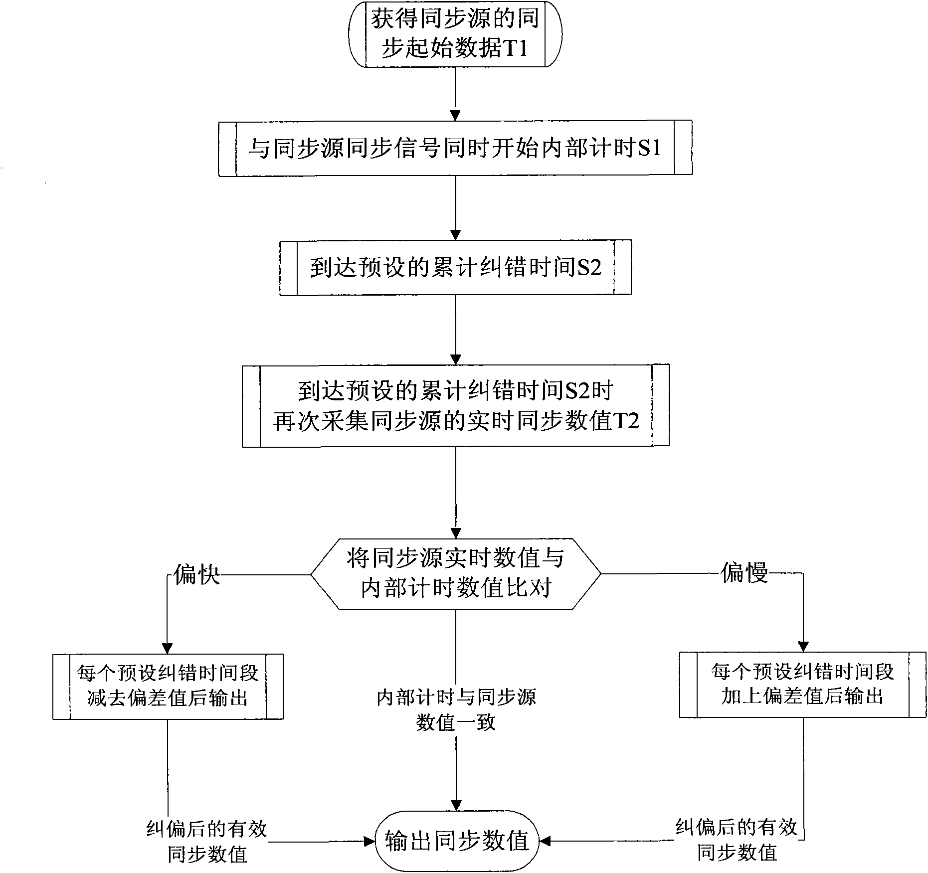
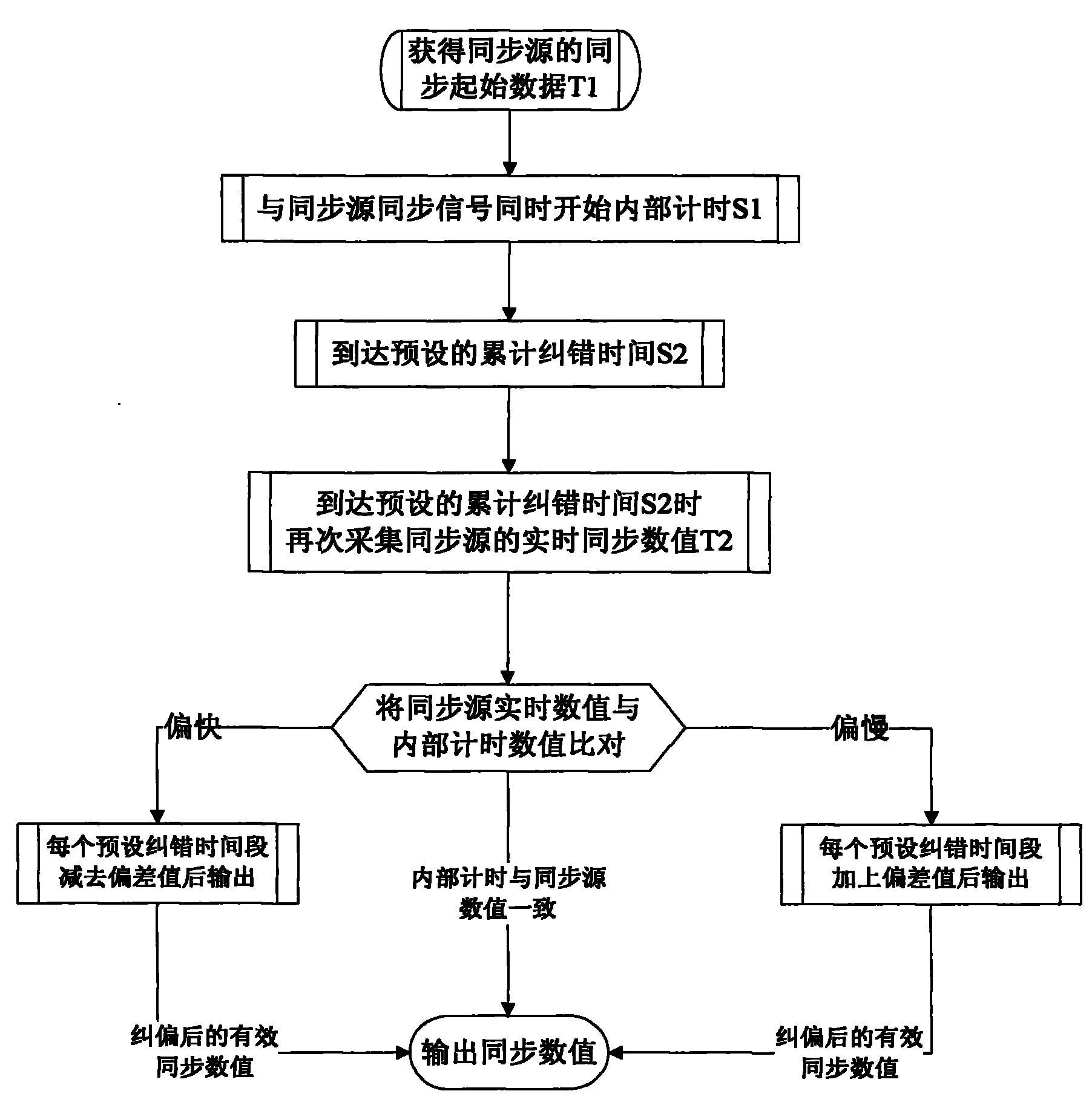
The invention discloses a synchronization error correction method. The method includes two steps, i.e. synchronization error detection and synchronization error correction; in the step of synchronization error detection, within fixed synchronization error detection time, the respective timing values of a synchronizer and a synchronization source in operation are simultaneously detected, and a synchronization error value between the synchronizer and the synchronization source is calculated according to the two timing values; in the step of synchronization error correction, after the synchronization error value is detected, whether the synchronizer is faster or slower than the synchronization source is first judged according to the negative or positive of the synchronization error value, and the synchronization error value is then subtracted from the synchronization value outputted by the synchronizer in operation within fixed time equal to the synchronization error detection time if the synchronizer is faster than the synchronization source, or is added with the synchronization value within the fixed time if the synchronizer is slower than the synchronization source. The invention overcomes the defects of the prior art, including short synchronization interval and no automatic synchronization error correction, and has the advantages of self-learning capability, low application cost, high synchronization reliability, wide application range and the like.
Description
technical field [0001] The invention relates to an error correction method, in particular to a synchronization error correction method, which is mainly used to make a discrete device self-correct the synchronization error and realize high synchronization with a synchronization source. Background technique [0002] Synchronization technology is widely used in daily life, and it is even more common in industrial fields. Synchronization in the prior art is usually achieved by means of a closed loop, such as adding a synchronous pulse to the signal source, and the upper control system realizes synchronous control of the discrete devices, and the discrete devices in the system are controlled by transmitting wireless synchronous control signals or wired control methods. device or devices on the same line to achieve synchronization. The above-mentioned discrete devices are basically a closed-loop synchronization mode based on upper-level control. The advantage of this mode is that...
Claims
Login to View More Application Information
Patent Timeline
 IPC IPC(8): H04L7/00
Inventor 陈秋玲
Owner 陈秋玲
Features
- Generate Ideas
- Intellectual Property
- Life Sciences
- Materials
- Tech Scout
- Unparalleled Data Quality
- Higher Quality Content
- 60% Fewer Hallucinations
Learn More Browse by: Latest US Patents, China's latest patents, Technical Efficacy Thesaurus, Application Domain, Technology Topic, Popular Technical Reports.
© 2025 PatSnap. All rights reserved.Legal|Privacy policy|Modern Slavery Act Transparency Statement|Sitemap|About US| Contact US: help@patsnap.com