

Shallow poor subsoil composite foundation stabilization treatment method
A composite foundation and treatment method technology, applied in the field of geotechnical engineering, can solve the problems that the treatment method of a large-scale weak foundation cannot fully meet the requirements, the depth of the pile body is too deep, and the construction machinery is cumbersome. The effect of reducing post-construction settlement and miniaturizing construction equipment
- Summary
- Abstract
- Description
- Claims
- Application Information
AI Technical Summary
Benefits of technology
Problems solved by technology
Method used
Image

Examples
Embodiment 1
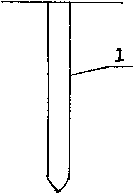
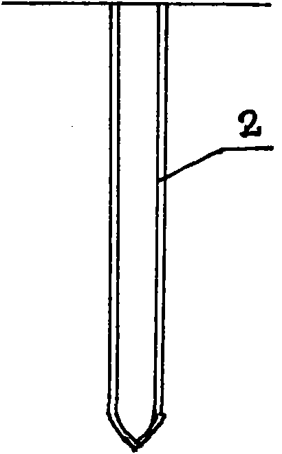
[0027] As shown in Figure 1, the geotechnical pipe bag laying steps: (1) as Figure 1a , use Luoyang shovel to form the hole, the hole forming standard: diameter Φ120mm, depth 4m, pile spacing 0.6m, triangular arrangement; (2) such as Figure 1b , Use the drill pipe to send the closed end of the geotechnical pipe bag with a diameter of 180mm and a length of 4.5m to the bottom of the hole.
[0028] The preparation steps of lime-mixed clay mixed filling material are as follows: (1) Select fresh block ash, water it for pre-digestion and pass it through a 5mm sieve; mix clay with clay excavated in situ, clay particles ≤ 15mm, remove visible organic matter cohesive soil (2) Lime and clay are mixed evenly in the mixing equipment according to the designed lime-soil ratio, and the amount of quicklime added is 8%.
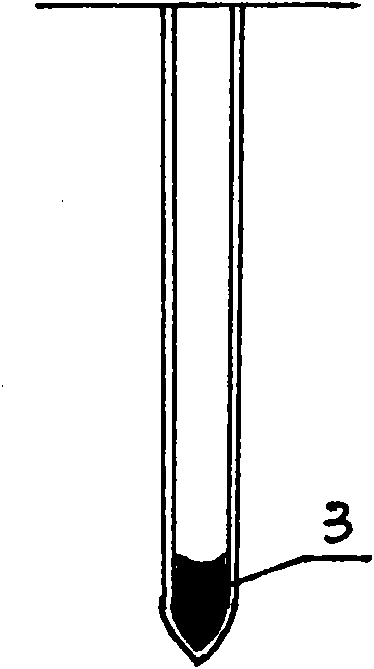
[0029] Such as Figure 1c and Figure 1d , The construction steps of compaction and compaction are: after mixing evenly, the lime soil filler is filled in layers along th...
PUM
| Property | Measurement | Unit |
|---|---|---|
| Diameter | aaaaa | aaaaa |
| Strength | aaaaa | aaaaa |
| Diameter | aaaaa | aaaaa |
Abstract
Description
Claims
Application Information