
Imaging velocity analysis method of seismic scattering P-S converted wave

A technology of seismic scattering and imaging velocity, which is applied in seismic signal processing and other directions, and can solve problems such as errors, velocity parameters and imaging effect errors, and inaccurate velocity parameters.

Inactive Publication Date: 2012-09-05
XI'AN PETROLEUM UNIVERSITY
View PDF0 Cites 0 Cited by
  • Summary
  • Abstract
  • Description
  • Claims
  • Application Information

AI Technical Summary

Problems solved by technology

The time-distance curve of the reflected converted wave is neither symmetrical nor hyperbolic to the common conversion point. The traditional hyperbolic approximation is not applicable to the converted wave at all. Inherent characteristics of the distance relationship: first, even if it is a horizontal reflection layer of a uniform medium, the horizontal position of the conversion reflection point of the converted wave changes with the offset, the depth of the reflection layer, and the ratio of longitudinal and transverse waves; second, the reflection The time-distance curve of the converted wave is not a hyperbola. If the hyperbolic time-distance relationship is used for velocity analysis, the correct shear-wave velocity value will not be obtained, especially for medium-shallow layers and large offsets. In addition, Common conversion point CCP gather processing technology is a set of processing technology developed for the horizontal layered homogeneous medium model, but it has not yet realized the real common conversion point gather selection and velocity analysis and superimposed imaging, only the target layer common conversion point Strictly speaking, this technology is only suitable for horizontal layered uniform media, but in practice, this ideal situation is almost impossible to find, so there are large errors in the final velocity parameters and imaging effects; In addition, the reflection wave is very limited in the seismic wave component, and the propagation law of the reflection wave is different from other components of the seismic wave. If the other components of the seismic wave are treated with the reflection theory, the velocity parameters obtained must be inaccurate

Method used


Image

  • Imaging velocity analysis method of seismic scattering P-S converted wave
  • Imaging velocity analysis method of seismic scattering P-S converted wave
  • Imaging velocity analysis method of seismic scattering P-S converted wave

Examples


Embodiment 1

[0111] Take a three-component actual seismic survey data containing 146 shots, 86 traces per shot, and 2000 sampling points per trace as an example to illustrate the implementation steps of this example:

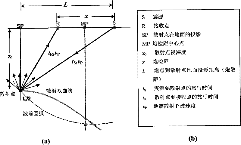
[0112] Step 1: read the P-P wave seismic data containing 146 shots, 86 traces per shot, and 2000 sampling points per trace into the two-dimensional array F, and load the observation system parameters into the trace header of the original seismic data, and based on Observation system and acquisition parameters calculate the location and coordinates of scattering points;

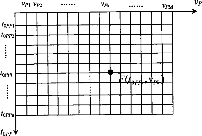
[0113] Step 2: According to the seismic scattering P-P wave time-distance hyperbolic equation, on the shot set, fix t 0PPi In the case of , choose a velocity v arbitrarily Pk , the speed can determine a hyperbolic trajectory, and superimpose or correlate the scattering amplitudes at each offset along the hyperbolic trajectory, and then weight and sum the energy of the same scattering point to obtain the cor...


PUM


Abstract

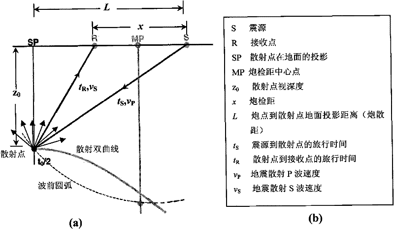
The invention relates to an imaging velocity analysis method of a seismic scattering P-S converted wave, comprising the following steps of: firstly, reading the seismic data of a seismic scattering P-P wave into a two-dimensional array F, and computing the position and the coordinate of a scattering point; secondly, arbitrarily selecting a velocity vPk to overlap or correlate scattering amplitudes of shot-geophone distances and weigh to sum the energy of the same scattering point so as to obtain a corresponding average amplitude; thirdly, making a seismic scattering P-P wave velocity spectrum; fourthly, reading the seismic data of the seismic scattering P-S converted wave into a two-dimensional array E, and computing the position and the coordinate of the scattering point; fifthly, taking an acquired seismic scattering P wave velocity to overlap or correlate the scattering amplitudes of the shot-geophone distances and weigh to sum the energy of the same scattering point so as to obtain the corresponding average amplitude; and sixthly, making a seismic scattering P-S converted wave velocity spectrum. The invention increases the overlapping times of a velocity analysis technology and enables the focusing capability of effective scattered wave energy to be higher.

Description

technical field [0001] The invention belongs to the technical field of seismic wave velocity parameter extraction and imaging processing, in particular to a seismic scattering P-S converted wave imaging velocity analysis method. Background technique [0002] Velocity is the basis of seismic wave propagation and one of the key factors in imaging. The accuracy of velocity acquisition is directly related to the accuracy of seismic wave imaging. The time-distance curve of the reflected converted wave is neither symmetrical nor hyperbolic to the common conversion point. The traditional hyperbolic approximation is not applicable to the converted wave at all. Inherent characteristics of the distance relationship: first, even if it is a horizontal reflection layer of a uniform medium, the horizontal position of the conversion reflection point of the converted wave changes with the offset, the depth of the reflection layer, and the ratio of longitudinal and transverse waves; second, ...

Claims


Application Information

Patent Timeline
Patent Type & Authority Patents(China)
IPC IPC(8): G01V1/28G01V1/30
Inventor 沈鸿雁
Owner XI'AN PETROLEUM UNIVERSITY
Learn More