Supercharge Your Innovation With Domain-Expert AI Agents!

Rotary connector

A rotary connector, conductive contact technology, applied in the direction of flexible/rotatable wire connectors, connections, rotary collectors, etc., can solve the problems of unstable rotating shaft, component damage, lack of durability, etc., to achieve reliability and The effect of high durability

Inactive Publication Date: 2010-09-15
EXCEL DENSHI
View PDF2 Cites 5 Cited by
  • Summary
  • Abstract
  • Description
  • Claims
  • Application Information

AI Technical Summary

Problems solved by technology

[0010] Therefore, the rotating shaft is unstable, and when rotating at a high speed, the electrodes on the plug side in the contact state are separated from the conductive contact terminals on the socket side, so that the energized state is interrupted, which lacks reliabil

Method used


Image

  • Rotary connector
  • Rotary connector
  • Rotary connector

Examples


Embodiment Construction

[0025] Hereinafter, embodiments of the present invention will be described in detail with reference to the drawings. The rotary connector according to this embodiment is composed of a combination of a multi-pole plug and a multi-pole socket.

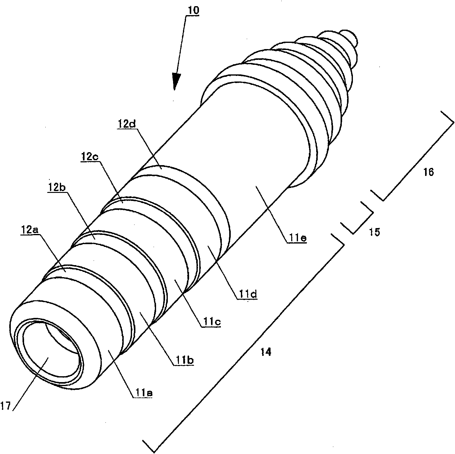
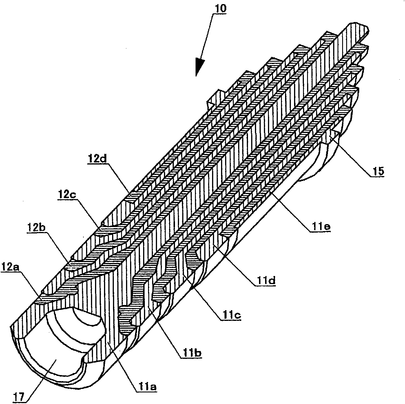
[0026] First, according to figure 1 with figure 2 , the structure of the multi-pole plug constituting the rotary connector according to this embodiment will be described. figure 1 It is a perspective view of the multi-pole plug related to this embodiment, figure 2 It is a cross-sectional perspective view of the multi-pole plug according to this embodiment.

[0027] Such as figure 1 with figure 2 As shown, the multi-pole plug 10 has: first to fifth electrodes 11a-11e made of conductive metal; and first to fourth insulating collars 12a made of insulating resin for insulating the electrodes 11 ~12d. In addition, the following parts are formed by these electrodes 11 and insulating collar 12: rod-shaped mandrel part 14, which is a p...


PUM


Abstract

The object of the invention is to provide a rotary connector which performs conductive connection, in which one connector component can relatively be rotated with respect to the other connector component and which has high reliability and durability. The rotary connector (1) is provided with a multipolar plug (10) and a multipolar jack (20). A plurality of electrodes (11a to 11e) are sequentially exposed in a core part (14) of the multipolar plug (10) in an axial direction across insulating collars (12a) to (12d). A bearing (17) is formed at a tip of the core part (14) of the multiplolar plug (10). The multipolar jack (20) is provided with two groups of conductive terminals (23a to 23e) and (24a to 24e) which are brought into conductive contact with the electrodes (11), and a rotary shaft (25) arranged at the back of a plug storage space. When the multipolar plug (10) and the multipolar jack (20) are connected, the rotary shaft (25) can rotatably be supported by the bearing (17).

Description

technical field [0001] The present invention relates to an electrical connector for electrical wiring connection, and more particularly to a rotary connector in which one connector part is rotatable relative to the other connector part. Background technique [0002] In the past, in the first device and the second device that move relatively, when it is necessary to exchange electrical signals between the two devices, the two devices are electrically connected by using cables or flexible printed circuit boards in many cases. [0003] However, if the first device and the second device are relatively rotated by 360° or more, the wiring may be broken if the substrate is flexible, and even the cables may be disconnected if they are rotated multiple times. Therefore, for example, in a biaxial hinge-type folding mobile phone, a structure in which the main body side and the display side are relatively rotated more than 360° cannot be adopted. [0004] On the other hand, as electric...

Claims


Application Information

Patent Timeline
IPC IPC(8): H01R24/02H01R39/00
CPCH01R24/58H01R2107/00H01R39/64H01R35/04
Inventor 藤井一志弓立伸也
Owner EXCEL DENSHI
Features
  • R&D
  • Intellectual Property
  • Life Sciences
  • Materials
  • Tech Scout
  • Unparalleled Data Quality
  • Higher Quality Content
  • 60% Fewer Hallucinations
Learn More