Automatic clutch device in electric screwdriver

An electric screwdriver, automatic clutch technology, used in screwdrivers, wrenches, manufacturing tools, etc., can solve problems such as no clutch device, transmission components and motor damage.

Inactive Publication Date: 2012-05-09
张辉
View PDF0 Cites 0 Cited by
  • Summary
  • Abstract
  • Description
  • Claims
  • Application Information

AI Technical Summary

Problems solved by technology

[0002] The structure of the existing electric screwdrivers is that the motor drives the drive shaft to directly connect the transmission shaft and the cutter head assembly. There is no clutch device in the middle. When the screw is turned in place, the cutter head is blocked by the screw and cannot rotate. Continue to drive the transmission shaft and the cutter head assembly to rotate. In this way, the reverse torsional force formed is easy to cause damage to the transmission assembly and the motor. In view of this, how to design an automatic clutch device between the cutter head assembly and the motor of the electric screwdriver To protect becomes a technical problem to be solved

Method used


Image

  • Automatic clutch device in electric screwdriver
  • Automatic clutch device in electric screwdriver
  • Automatic clutch device in electric screwdriver

Examples


Embodiment Construction

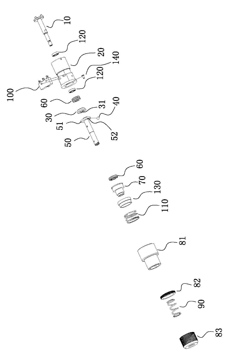
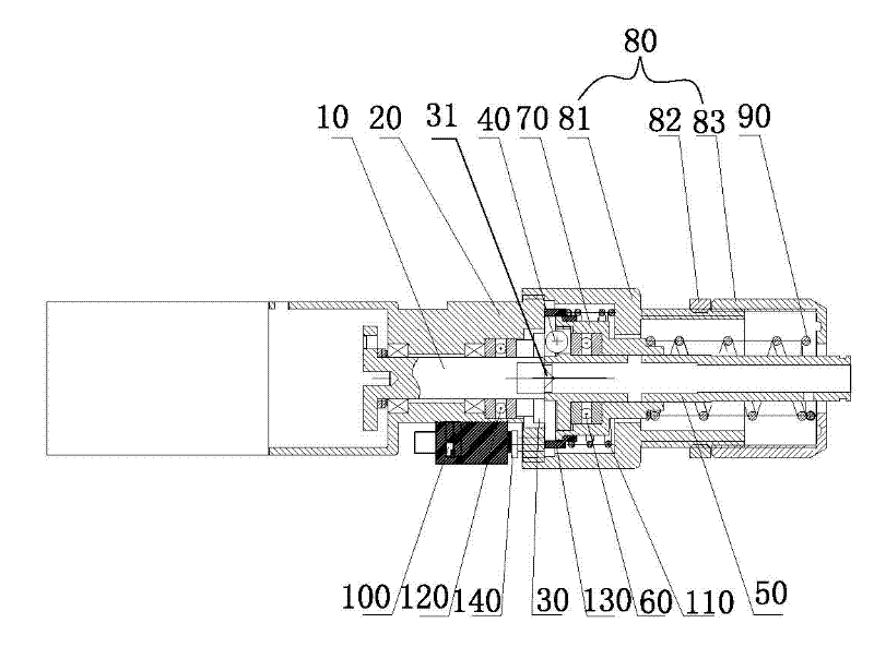
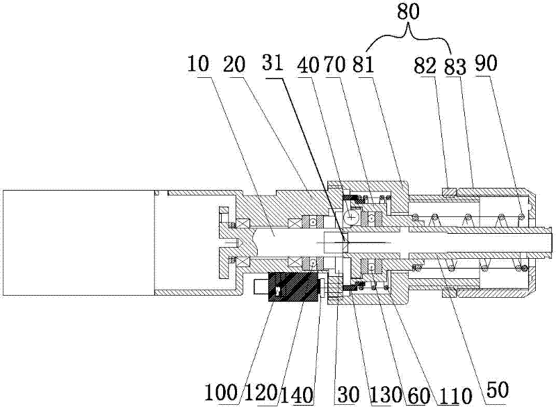
[0012] Such as Figure 1-2 As shown, the present invention includes: an automatic clutch device in an electric screwdriver, including: a drive shaft 10, a clutch barrel 20, a stop cam 30, a transmission ball 40, a transmission shaft 50, a thrust bearing 60, a spring seat 70, The shell assembly 80, the torsion spring 90, the micro switch 100, the drive shaft 10 is installed in the clutch barrel 20, the rear end of the drive shaft 10 is connected with the output shaft of the motor through the transmission device, and the front end of the drive shaft 10 is fixedly connected with a stop The eccentric position of the end face of the cam 30 and the stop cam 30 is formed with a stop drive block 31; the connecting end of the shell assembly 80 is fixedly connected with the clutch cylinder 20 by one or more parts, and is respectively in the cavity of the shell assembly 80. Installed with transmission ball 40, transmission shaft 50, thrust bearing 60, spring seat 70, torsion spring 90, t...


PUM


Abstract

The invention relates to the technical field of the electric tool, in particular to an automatic clutch device in an electric screwdriver. A clutch device is added in an electric screwdriver, a transmission ball is stirred by a stalling cam to drive a transmission shaft to rotate, when a screw rotates in place, a tool bit and the transmission shaft are suffered a counter twisting force, so the stalling cam compresses the transmission ball into a through hole of a flange plate on one end of the transmission shaft, the transmission ball drives a spring seat to move in the axial direction so as to trigger a micro switch, a motor is powered off and stops rotation, and the automatic clutch function is realized. In addition, the twisting force of a shell jacket component can be adjusted according to the real twisting force of the stalling cam, so the transmission ball can be successfully put by a stalling drive block on the stalling cam into the through hole. The automatic clutch device overcomes the weakness that after unscrewing the screw, the present electronic screwdriver cannot be automatically stopped and is easy to damage, and has the advantages of ingenious and compact structure, convenient application and automatic clutch.

Description

technical field [0001] The invention relates to the technical field of electric tools, in particular to an automatic clutch device in an electric screwdriver. Background technique [0002] The structure of the existing electric screwdrivers is that the motor drives the drive shaft to directly connect the transmission shaft and the cutter head assembly. There is no clutch device in the middle. When the screw is turned in place, the cutter head is stuck by the screw and cannot rotate. Continue to drive the transmission shaft and the cutter head assembly to rotate. In this way, the reverse torsional force formed is easy to cause damage to the transmission assembly and the motor. In view of this, how to design an automatic clutch device between the cutter head assembly and the motor of the electric screwdriver To protect becomes a technical problem to be solved. Contents of the invention [0003] The object of the present invention is to provide a novel and compact automati...

Claims


Application Information

Patent Timeline
Patent Type & Authority Patents(China)
IPC IPC(8): B25B23/00B25B23/157
Inventor 张辉
Owner 张辉
Why Eureka
Try Eureka