Electric clutch type winch

A clutch-type, electric technology, applied in hoisting devices, clockwork mechanisms, etc., can solve the problems of unusable and exhausted automatic clutch devices, and achieve the effect of simple and reasonable structure, low power consumption and strong practicability

Inactive Publication Date: 2017-07-21
NINGBO ZHONGHUANG MACHINE & ELECTRICS
View PDF10 Cites 0 Cited by
  • Summary
  • Abstract
  • Description
  • Claims
  • Application Information

AI Technical Summary

Problems solved by technology

[0006] Its biggest defect is that when the device is in the "off" state, the electromagnetic coil must be kept energized for a long time, because the current is also large when there is a load, which will inevitably generate more heat energy. As time increases, the temperature of the electromagnetic coil will also increase. The higher it is, the magnetic force it generates will fail as the temperature of the electromagnetic coil rises until it fails, causing the automatic clutch device to be unusable

Method used


Image

  • Electric clutch type winch
  • Electric clutch type winch
  • Electric clutch type winch

Examples


Embodiment 1

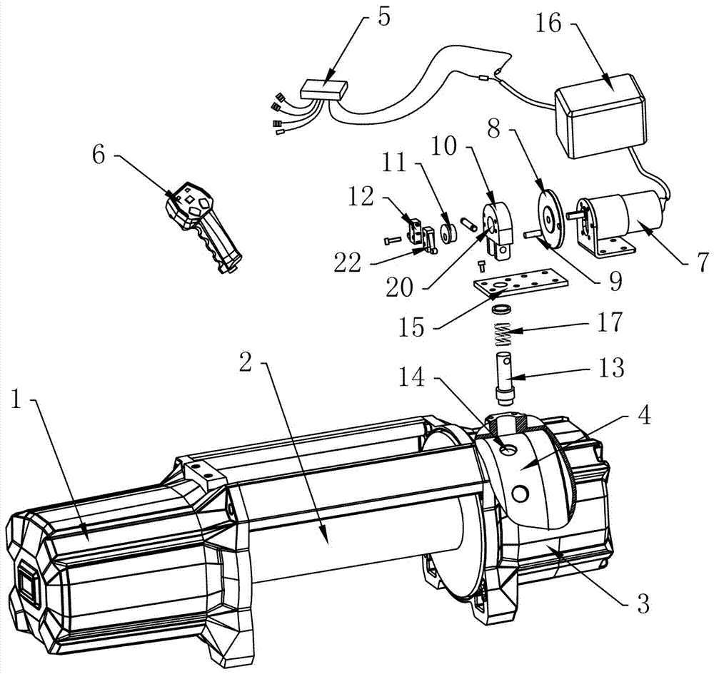
[0028] Embodiment one, such as Figure 1 to Figure 5 As shown, an electric clutch type winch includes a motor 1, a hoist drum 2 and a gear box 3, the hoist drum 2 is arranged between the motor 1 and the gear box 3, the hoist drum 2 is provided with a transmission shaft, and the gear box 3 is equipped with a deceleration mechanism, the deceleration mechanism includes a planetary deceleration assembly connected to the hoist drum 2, a small inner ring gear 4 sleeved outside the planetary deceleration assembly, the small internal gear 4 meshes with the planetary deceleration assembly, and the transmission shaft The front end is connected to the output shaft of the motor 1, and the rear end of the transmission shaft is connected to the planetary reduction assembly. The gearbox 3 is provided with a clutch control device. The clutch control device includes a direct pin 13, and one end of the direct pin 13 extends into the gearbox 3. , and the outer wall of the small inner ring gear 4...

Embodiment 2

[0032] Embodiment two, such as Figure 6 As shown, the difference from Embodiment 1 is that the eccentric member includes a turntable 8 and an eccentric shaft 18, the center of the turntable 8 is fixedly connected to the output shaft of the geared motor 7, one end of the eccentric shaft 18 is eccentrically fixed to the turntable 8, and the other end Extend into the linkage hole 20.

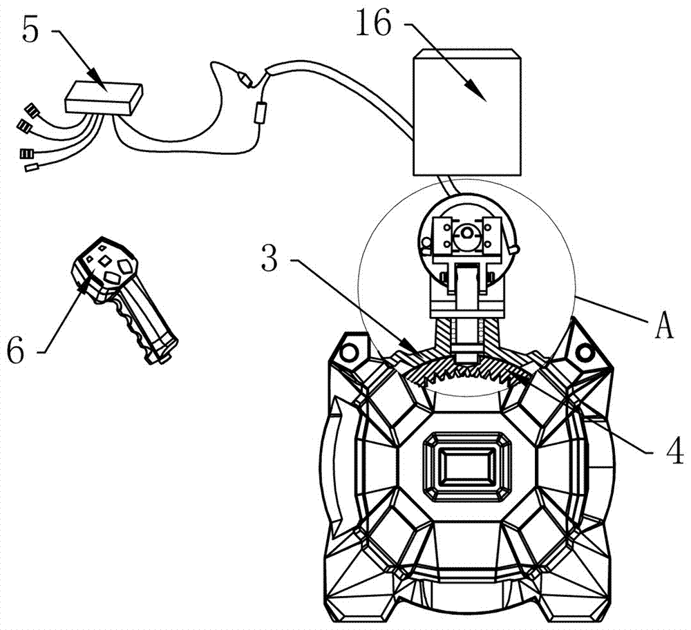
[0033] The working principle of this embodiment is to use the remote control 6 to drive the reduction motor 7 to work, the reduction motor 7 drives the turntable 8 to rotate, and the eccentric shaft 18 makes the linkage frame 10 move up and down, so as to drive the direct pin 13 to limit and cooperate with the small inner ring gear 4 or Break away from the limit fit, so that the clutch control device realizes the automatic clutch function, set the trigger lever 9, after touching the limit switch 12 each time, the power supply of the geared motor 7 can be automatically cut off

Embodiment 3

[0034] Embodiment three, such as Figure 7 As shown, the difference from Embodiment 1 is that the control mechanism is a time control module 19 integrated in the control circuit of the signal receiver 5 .

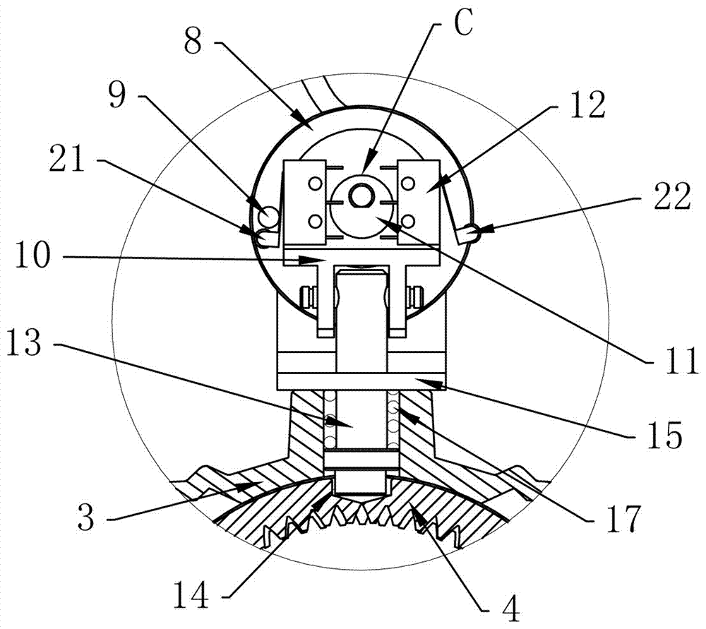
[0035] The working principle of this embodiment is to use the remote control 6 to drive the geared motor 7 to work, and the geared motor 7 drives the eccentric wheel 11 to rotate, so that the linkage frame 10 moves up and down, and drives the direct pin 13 to cooperate with the small inner ring gear 4 or to break away from the limit Cooperate, so that the clutch control device realizes the automatic clutch function, set the time control module 19, after the signal receiver 5 receives the instruction from the remote controller 6, the reduction motor 7 rotates, and the eccentric wheel 11 rotates at the same time, the linkage frame 10 rises, and the eccentric The highest point of the wheel 11 reaches the top dead center C, and now the signal receiver 5 automatically cuts off t...


PUM


Abstract

The invention relates to an electric clutch type winch. The electric clutch type winch comprises a motor, a hoisting drum and a gear box, wherein the hoisting drum is arranged between the motor and the gear box; a transmission shaft is arranged in the hoisting drum; a speed reducing mechanism is arranged in the gear box and comprises a planetary speed reducing component in transmission connection with the hoisting drum and an inner tooth ring sleeved outside the planetary speed reducing component; the inner tooth ring is meshed with the planetary speed reducing component; the front end of the transmission shaft is in transmission connection with an output shaft of the motor; the rear end of the transmission shaft is in transmission connection with the planetary speed reducing component; a clutch control device is arranged on the gear box and comprises a vertical pin, a speed reducing motor, a linkage frame and a control mechanism used for controlling operation of the speed reducing motor; the speed reducing motor is fixed on the gear box; the linkage frame is fixedly connected with the vertical pin; a linkage hole is formed in the linkage frame; an eccentric part in transmission connection with the speed reducing motor is movably arranged in the linkage hole. The electric clutch type winch is simple and reasonable in structure, low in power consumption, safe to use and high in practicability, and does not need to be powered on for a long time; the motor is low in possibility of heating.

Description

technical field [0001] The invention relates to the technical field of winches, in particular to an electric clutch winch. Background technique [0002] The winch is a self-protection and towing device for vehicles and boats. It can be used for self-rescue and rescue in harsh environments such as snow, swamps, deserts, beaches, and muddy mountain roads, and can be used for clearing obstacles, dragging items, and installing facilities under other conditions. It is an indispensable safety device for military police, petroleum, hydrology, environmental protection, forestry, transportation, public security, frontier defense, fire protection and other outdoor sports. [0003] The main structure of the electric winch usually includes a motor and a gearbox connected by a bracket. A reduction mechanism is provided in the gearbox. A winch connected to the reduction mechanism is provided between the motor and the gearbox. , one end of the transmission shaft is connected to the output...

Claims


Application Information

Patent Timeline
Patent Type & Authority Applications(China)
IPC IPC(8): B66D1/12B66D1/40
CPCB66D1/12B66D1/40
Inventor 曹科定毛秀挺杨刚
Owner NINGBO ZHONGHUANG MACHINE & ELECTRICS
Why Eureka
Try Eureka