
Valve rocker for automobile engine

A technology of automobile engine and valve rocker arm, which is applied to engine components, machines/engines, mechanical equipment, etc., can solve the problems of easy heat damage, loud noise, and easy wear and tear of the convex part of the valve rocker arm, so that it is not easy to wear and tear. , the effect of long service life

Active Publication Date: 2015-04-22
NINGBO ZHONGHE AUTO PATS
View PDF8 Cites 4 Cited by
  • Summary
  • Abstract
  • Description
  • Claims
  • Application Information

AI Technical Summary

Problems solved by technology

The valve rocker arm of the prior art is generally cast iron, and one end of the valve rocker arm that depresses the valve push rod is provided with a raised portion. The rocker arm rotates along the main shaft, so the contact area between the protrusion of the valve rocker arm and the valve ejector rod is small, which makes the protrusion of the valve rocker arm easy to wear, and the protrusion of the valve ejector rod and the valve rocker arm There is a certain gap between the raised parts, and when the raised part of the valve rocker arm is pressed down, there will be a certain impact force on the valve ejector rod, which will accelerate the wear of the two, thereby shortening the service life of the valve rocker arm
[0003] In addition, the end of the valve rocker arm in contact with the cam on the crankshaft of the engine is generally equipped with a roller. The cam is in contact with the roller. When the roller rotates, if the surface of the roller is not well lubricated, it will be easily heated and damaged, resulting in the cam and the roller being in contact with each other. There is a lot of noise when the rollers are in contact with each other

Method used


Image

  • Valve rocker for automobile engine
  • Valve rocker for automobile engine
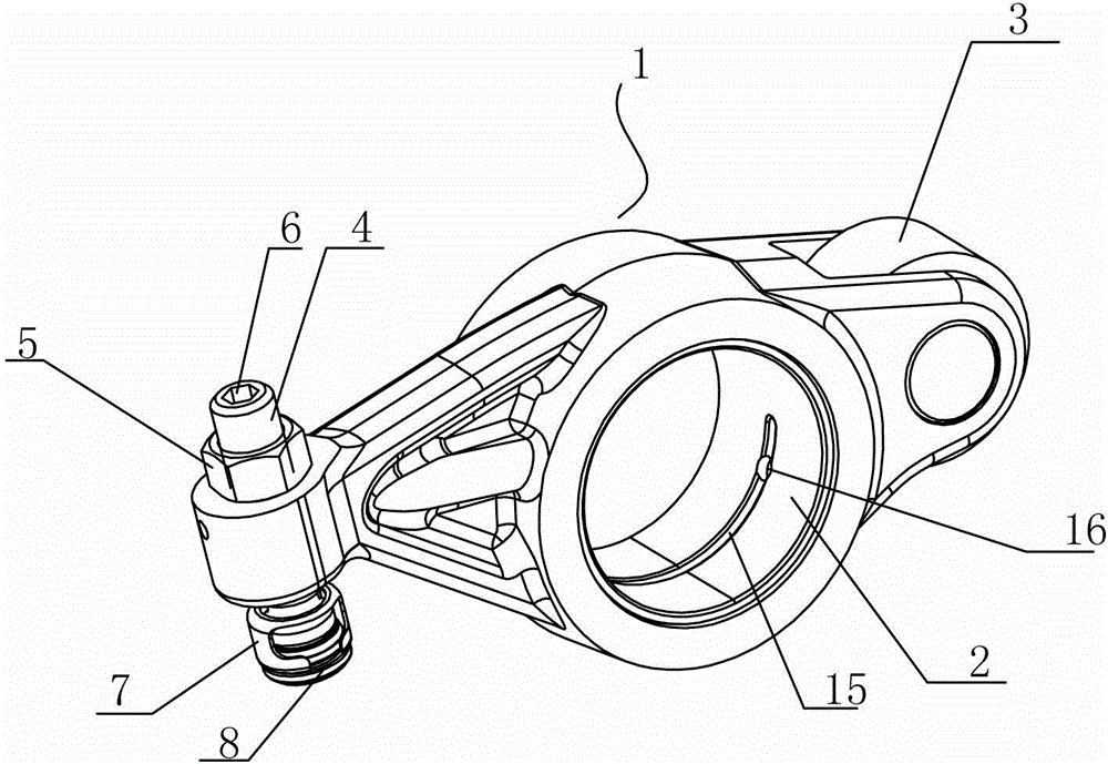
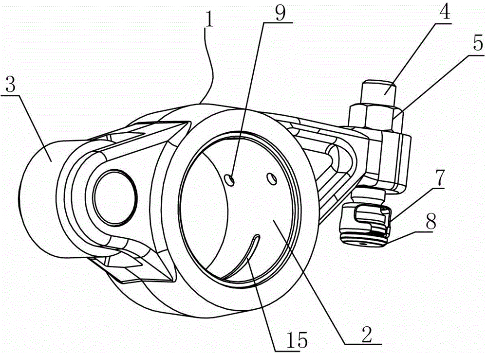
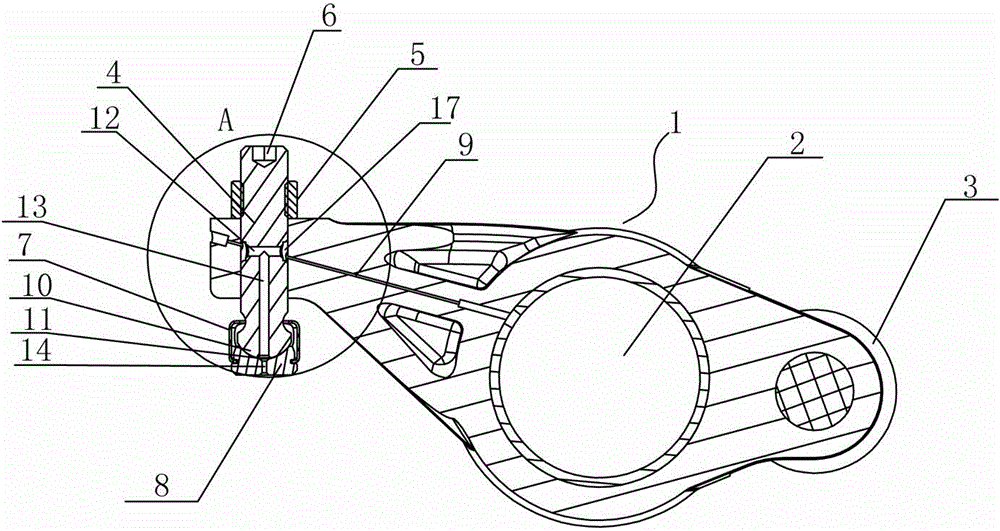
  • Valve rocker for automobile engine

Examples


Embodiment Construction

[0022] The present invention will be described in further detail below in conjunction with the accompanying drawings and specific embodiments.

[0023] like figure 1 , figure 2 , image 3 , Figure 4 and Figure 5 shown;

[0024] The valve rocker arm of the automobile engine of the present invention comprises a rocker arm body 1, which is provided with a shaft hole 2 that fits with the main shaft in clearance, and one end of the rocker arm body 1 is provided with a valve rod for supporting the valve. The push rod 4 for adjusting the valve clearance, and the other end of the rocker arm body 1 is provided with a roller 3 for contacting with the crankshaft cam of the engine. The lower end of the rod 4 is provided with a ball head 10, the ball head 10 is provided with a spacer 8, and the upper end surface of the spacer 8 is provided with a concave arc surface 11 whose shape and size match the surface of the ball head 10, so that A connecting frame 7 is arranged between the ...


PUM

PropertyMeasurementUnit
Thicknessaaaaaaaaaa

Abstract

The invention discloses a valve rocker for an automobile engine. The valve rocker comprises a rocker body which is provided with a shaft hole in clearance fit with a main shaft, one end of the rocker body is provided with an ejector rod used for ejecting a valve lifer and adjusting valve clearance, the other end of the rocker body is provided with a roller used for making contact with an engine crankshaft cam, the ejector rod is in threaded connection with a threaded hole in one end of the rocker body, a bulb is arranged at the lower end of the ejector rod and provided with a cushion block, the upper end face of the cushion block is provided with an inwards-concave arc surface with the shape and the size matched with those of the surface of the bulb, a connecting frame is arranged between the cushion block and the lower end of the ejector rod, the lower end of the ejector rod is sleeved with the upper end of the connecting frame in a sliding mode, swing clearance exists between the upper end of the connecting frame and the lower end of the ejector rod, and the lower end of the connecting frame is connected with the outer side wall of the cushion block. The valve rocker for the automobile engine is not prone to abrasion, long in service life and low in noise and makes contact with the valve lifter all the time.

Description

technical field [0001] The invention relates to the technical field of automobile engines, in particular to a valve rocker arm for an automobile engine. Background technique [0002] The valve rocker arm is an indispensable and important part of the automobile engine. It is installed on the main shaft, and there is a certain angle of rotation gap between the valve rocker arm and the main shaft. The rotation of the valve rocker arm is mainly used to adjust the valve clearance of the automobile engine. . When the engine crankshaft rotates, it drives the cam to rotate. There are many eccentric protruding parts on the cam corresponding to one end of each valve rocker arm, and the other end of the valve rocker arm corresponds to the engine valve push rod. When the cam rotates, the protruding part of the cam presses down on one end of the valve rocker arm, and the valve rocker arm rotates along the main shaft, so that the other end of the valve rocker arm presses down on the valv...

Claims


Application Information

Patent Timeline
IPC IPC(8): F01L1/18
CPCF01L1/181
Inventor 鲍德夫
Owner NINGBO ZHONGHE AUTO PATS
Learn More