Mechanical transmission of electric vehicle

A technology for mechanical transmissions and electric vehicles, applied in mechanical equipment, mechanical control devices, instruments, etc., to solve problems such as reduced power and torque, and easy burnout of motors and control systems

Inactive Publication Date: 2012-05-30
蔡旭阳
View PDF0 Cites 2 Cited by
  • Summary
  • Abstract
  • Description
  • Claims
  • Application Information

AI Technical Summary

Problems solved by technology

However, when the motor is adjusted to run at a low speed, its output power and torque will decrease correspondingly, making the electric vehicle powerless during the uphill process, and the current amplifies the motor to heat up when going uphill, making the motor and the control system easy to burn out

Method used


Image

  • Mechanical transmission of electric vehicle
  • Mechanical transmission of electric vehicle
  • Mechanical transmission of electric vehicle

Examples


Embodiment 1

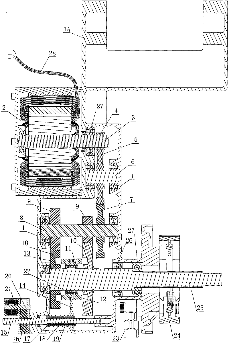
[0037] Such as Figure 1 to Figure 9 Shown is the first embodiment of the electric vehicle mechanical transmission of the present invention, the electric vehicle mechanical transmission includes a box body 1, the box body 1 is connected with a flat fork 1A, and the flat fork 1A is used to connect the entire machine to the vehicle frame superior.

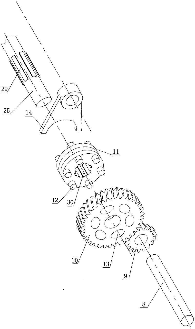
[0038] Such as figure 1 As shown in , the output shaft 25 is provided with at least two output gears 10, the output gears 10 can rotate on the output shaft 25, and the diameters of each output gear 10 are different. The main shaft 8 is correspondingly fixed with a driving gear 9 meshing with the output gear 10 for transmission. The present invention is provided with two output gears 10 on the output shaft 25, and the output gears 10 are installed on the output shaft 25 through a snap spring.

[0039] Such as figure 2 As shown in , the output shaft 25 is provided with a keyway 29, the driven sleeve 11 is set on the keyway 29, the...

Embodiment 2

[0053] Such as Figure 10 , Figure 11 Shown in is the second embodiment of the electric vehicle mechanical transmission of the present invention, which is different from Embodiment 1 in that the driven sleeve 11 is not arranged on the output shaft 25 but on the main shaft 8 .

[0054] Such as Figure 10 As shown in , the main shaft 8 is provided with at least two driving gears 9, the driving gears 9 can rotate on the main shaft 8, and the diameters of each driving gear 9 are different. The output shaft 25 is correspondingly fixed with the output gear 10 meshing with the drive gear 9 for transmission. The present invention is provided with two driving gears 9 on the main shaft 8, and the driving gears 9 are installed on the main shaft 8 through a snap spring.

[0055] Such as Figure 11 As shown in , the main shaft 8 is provided with a keyway 29, the driven sleeve 11 is set on the keyway 29, the driven sleeve 11 is provided with a keyway hole 30, the driven sleeve 11 can s...

Embodiment 3

[0069] Such as Figure 12 Shown in is the third embodiment of the electric vehicle mechanical transmission of the present invention, which is different from Embodiments 1 and 2 in that the driven sleeve 11 is not provided on the main shaft 8 or the output shaft 25, and the output shaft 25 and the high-speed output An electromagnetic clutch 42 is arranged between the gears 44 . The inner hole of the electromagnetic clutch 42 is provided with a spline, and the main shaft 8 cooperating with the spline also has a spline. The electromagnetic clutch 42 can move axially on the output shaft 25 .

[0070] Described output shaft 25 is provided with high-speed output gear 44, and high-speed output gear 44 can rotate on output shaft 25, and low-speed output gear 45 is then fixed on the output shaft 25, and the diameter of each output gear is different. The main shaft 8 is correspondingly fixed with a high-speed driving gear 46 meshing with the high-speed output gear 44. The low-speed driv...


PUM


Abstract

The invention belongs to the technical field of power drive of electric vehicles, and aims to achieve the goal that a motor is capable of outputting different vehicle speed and different torques at the same rotate speed. The invention provides a mechanical transmission of an electric vehicle, which comprises a box body; the box body is provided with a motor; the motor is provided with a motor shaft; the motor shaft is in drive connection with a main shaft; the main shaft is fixedly provided with a driving gear; the driving gear is in meshing drive with an output gear sheathed onto an output shaft; the output gear is capable of rotating on the output shaft; the output shaft is provided with a driven sleeve; the driven sleeve can be connected with the output gear to drive the output shaft to rotate together when moving on the output shaft; the driven sleeve is provided with a shifting fork; and the shifting fork is connected with a regulating stem which is used for driving the driven sleeve to slide on the output shaft and is in connection drive with the output gear.

Description

technical field [0001] The invention belongs to the technical field of electric vehicle power transmission. Background technique [0002] The driving power of the existing electric vehicle is mainly changed by adjusting the voltage and current input to the motor and changing the speed of the motor. However, when the motor is adjusted to run at a low speed, its output power and torque are correspondingly reduced, making the electric vehicle weak during the uphill process, and the current amplifies the motor to generate heat during uphill, which makes the motor and the control system easy to burn out. Contents of the invention [0003] In order to solve the above-mentioned deficiencies, the purpose of the present invention is to provide a simple structure, small size, and can obtain different vehicle speeds and different torques under the same rotational speed at the same time. The efficiency is higher so as to achieve the energy-saving effect. In addition, when the gear is...

Claims


Application Information

Patent Timeline
Patent Type & Authority Applications(China)
IPC IPC(8): F16H3/08F16H3/10F16H63/32
Inventor 蔡贵席
Owner 蔡旭阳
Why Eureka
Try Eureka