Indoor high-voltage isolating switch static contact

A technology of isolating switch and internal high voltage, which is applied in the direction of electric switch, contact, contact heating/cooling, etc. It can solve the problems of high resistance of assembly contact surface, heating of switch operation state, burning out of contact fingers and contact seats, etc., and achieves Reduce production difficulty and cost, prolong service life and reduce contact resistance

Inactive Publication Date: 2012-08-15
浙江纪元高压电器开关有限公司
View PDF4 Cites 4 Cited by
  • Summary
  • Abstract
  • Description
  • Claims
  • Application Information

AI Technical Summary

Problems solved by technology

However, the static contact of this structure has the following problems in practical application: first, due to the overall structure of the static contact, it is difficult to be used in high-current isolation switchgear above 4000A; The processing and assembly requirements of the spherical contact surface of the contact seat are very high, especially the size and accuracy of the chamfer of the edge of the hole on the contact seat is not easy to control. Heating phenomenon occurs in the running state, and sometimes even burns out the contact fingers and contact seats

Method used


Image

  • Indoor high-voltage isolating switch static contact
  • Indoor high-voltage isolating switch static contact
  • Indoor high-voltage isolating switch static contact

Examples


Embodiment Construction

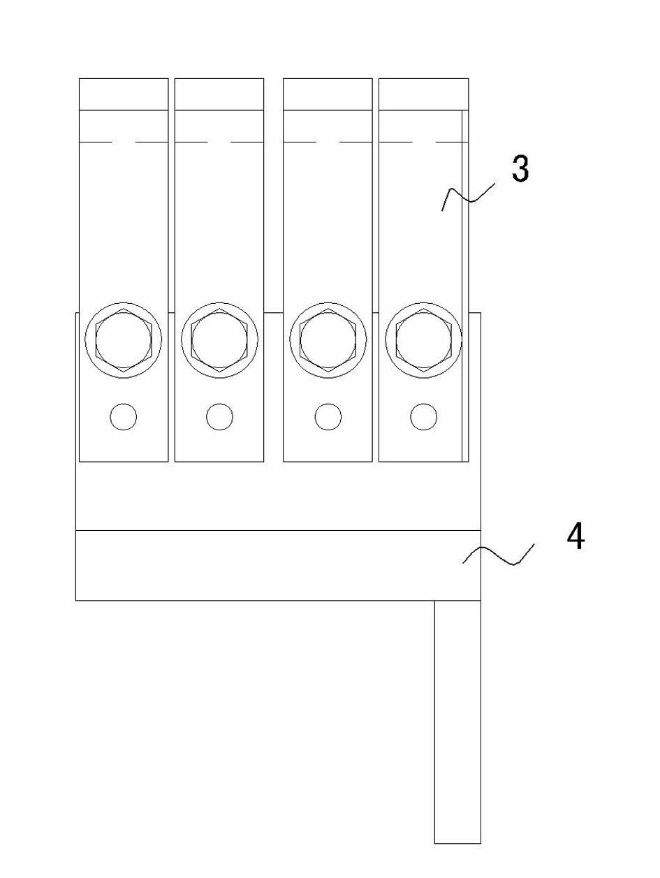
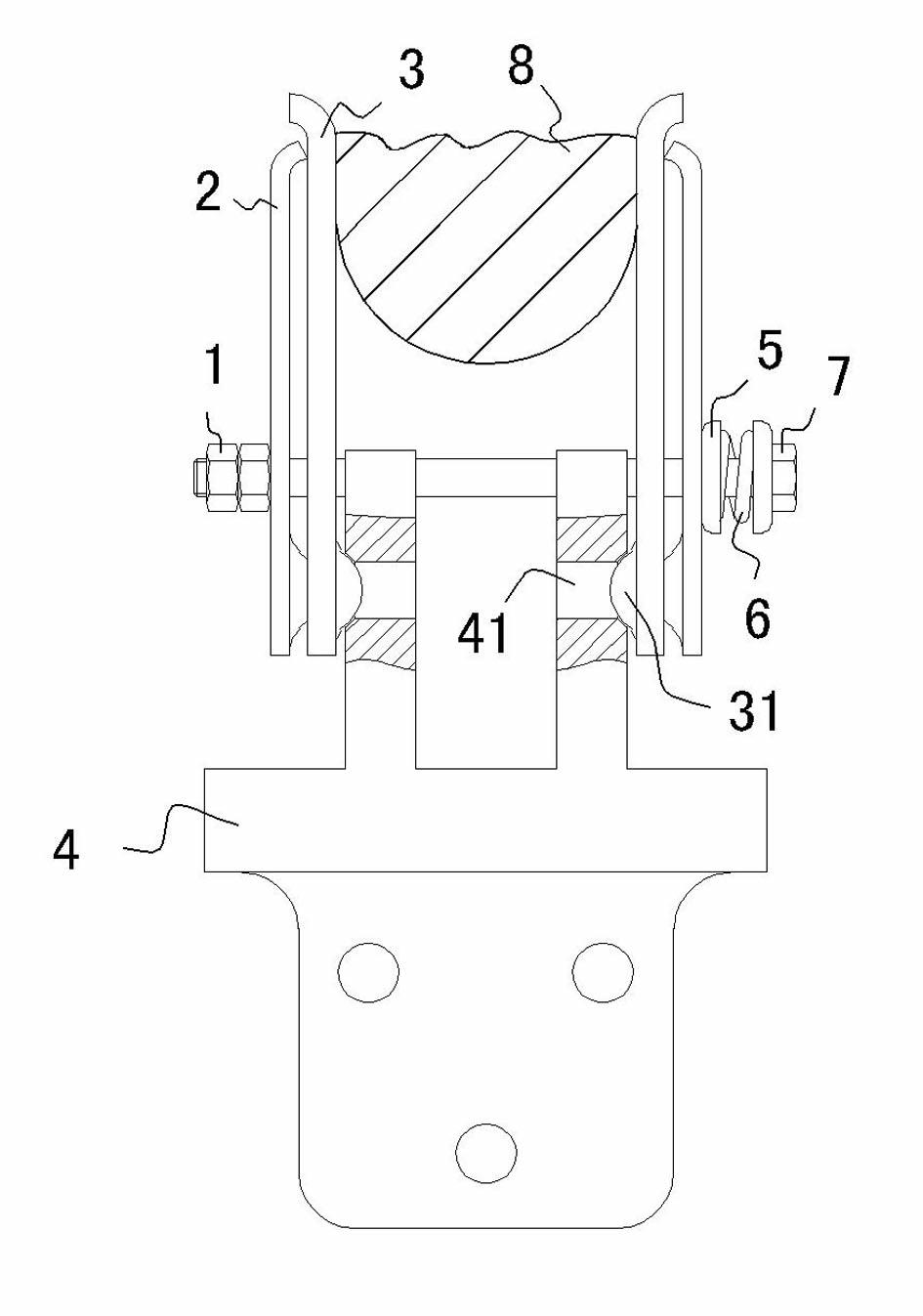
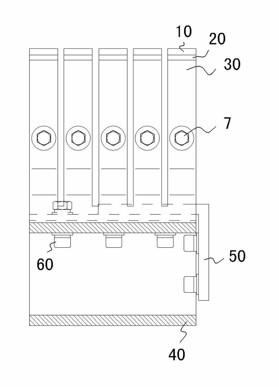
[0021] see image 3 , Figure 4 . The five pairs of contact fingers 10 are generally flat-bottomed U-shaped parts, and are integral elements, and the bottom of the contact finger 10 is enlarged along the axial direction of the screw rod 7, which is conducive to improving stability and expanding the contact surface. The integral contact finger 10 is formed by stamping with a special mold, and has good consistency. Matching the shape of the outer wall of the flat-bottomed U-shaped piece, the splint 20 is in close contact with the outer wall of the flat-bottomed U-shaped piece. The waist of contact finger 10, splint 20 and magnetic lock plate 30 is elastically locked by nut 1, spring seat 5, spring 6, and screw rod 7. The assembly is all very convenient for processing and assembling, and has low requirements.

[0022] The contact seat 40 is located at the bottom of the contact finger 40 and is made of a 140x100x10 square copper profile. Compared with the original contact seat...


PUM


Abstract

The invention discloses an indoor high-voltage isolating switch static contact comprising a plurality of pairs of contact fingers and magnetic lock plates, wherein the contact fingers share a contact seat and are abreast arranged at both sides of screw rods; and the magnetic lock plates are positioned at the outer sides of the contact fingers. The indoor high-voltage isolating switch static contact is characterized in that the plurality of pairs of abreast arranged contact fingers are integral type flat bottom U-shaped pieces; when specific construction is carried out, clamp plates are arranged on the outer wall of the flat bottom U-shaped pieces in closed mode; and the clamp plates and the flat bottom U-shaped pieces are fastened on the contact seat together by fastening pieces. In the indoor high-voltage isolating switch static contact, innovative improvements are made aiming at the problems that crimp connection is adopted by the contact fingers and the contact seat of the existing static contact, processing and assembly requirements are high, the size and the precision of chamfering of orifice edge is difficult to control and the resistance of contact surface is easy to be large. With the adoption of the contact fingers with the structure of the integral type flat bottom U-shaped pieces and the technical scheme that the contact seat and the contact fingers are directly connected by the fastening pieces, the problem caused by contact of the spherical surface and an orifice edge line in the prior art is solved, and the purposes of reliable contact, low contact resistance, difficult heating and the like are achieved so that a product is suitable for operation in a site the rated current of which is larger than 4000A.

Description

【Technical field】 [0001] The invention relates to a static contact of an indoor high-voltage isolating switch. 【Background technique】 [0002] High-voltage isolating switches are often used to divide, close and isolate circuits when there is voltage in the power transmission and distribution circuit without load, and this function is mainly based on the effective connection between the moving contact and the static contact. The static contact is composed of two parts, the contact finger and the contact seat. The contact fingers stamped by copper plate are divided into two independent rows, and are elastically and fixedly installed in pairs side by side in the static contact seat. When in use, the moving contact stretches the contact fingers on both sides with the help of running impact force, and the two fully contact to realize the conductive function. [0003] figure 1 , figure 2 The structure of the existing static contact is shown. The contact fingers 3 on both side...

Claims


Application Information

Patent Timeline
Patent Type & Authority Applications(China)
IPC IPC(8): H01H1/50H01H1/62
Inventor 傅建平王志文
Owner 浙江纪元高压电器开关有限公司
Why Eureka
Try Eureka