
Piezoelectric transformer with arch structure

A piezoelectric transformer and arched structure technology, applied in the field of transformers, can solve the problems of inconvenient welding of side electrodes, large area of ​​remaining tiles, increased power loss, etc., and achieve the effects of less heat generation, large output power, and reduced loss

Inactive Publication Date: 2010-02-03
北京为华新光电子有限公司
View PDF0 Cites 4 Cited by
  • Summary
  • Abstract
  • Description
  • Claims
  • Application Information

AI Technical Summary

Problems solved by technology

At present, most of the existing radial transformers have a square or circular structure. Especially for circular transformers, it is not very convenient to weld the side electrodes. The coverage rate is not high, so the area of ​​the remaining tiles is too large, the utilization rate is not high, and the power loss is increased

Method used


Image

  • Piezoelectric transformer with arch structure
  • Piezoelectric transformer with arch structure
  • Piezoelectric transformer with arch structure

Examples


Embodiment Construction

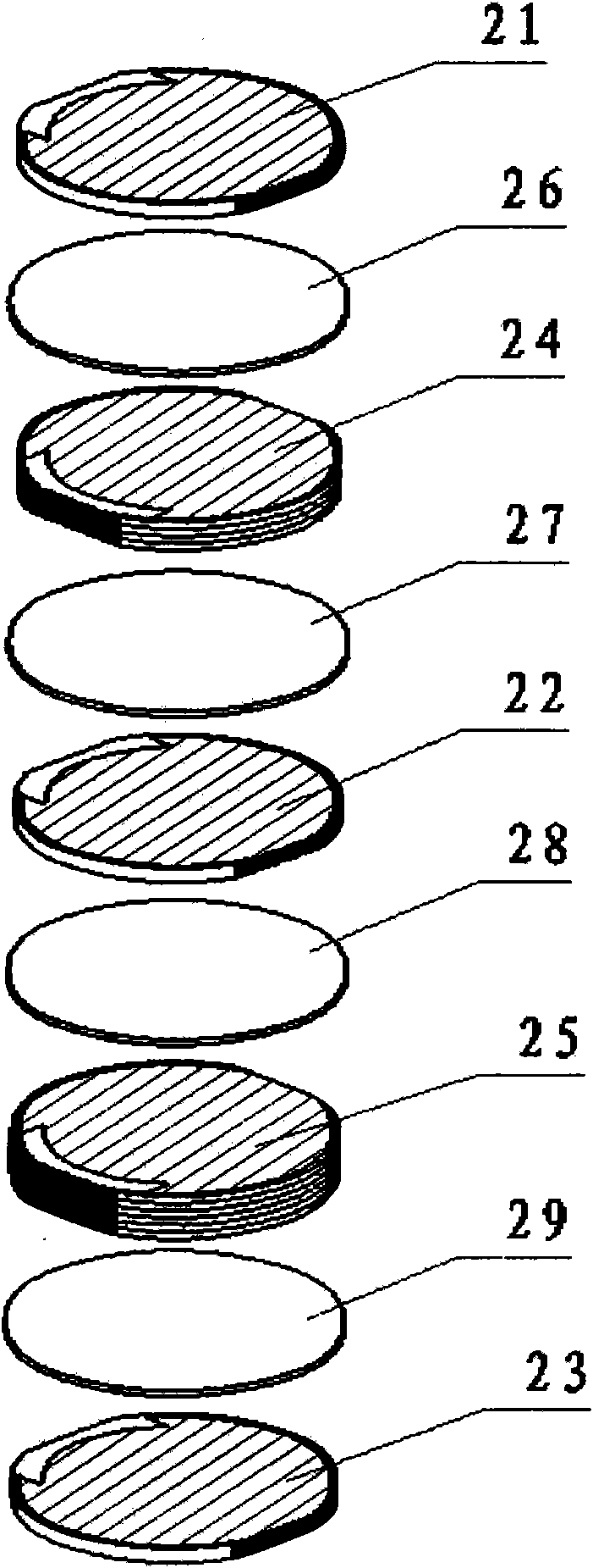
[0026] The main idea of ​​the present invention is to form piezoelectric transformers of various structural forms by arranging the piezoelectric sheets in an arched structure, and then stacking the piezoelectric sheets of the arched structure layer by layer, so that a better surface of the piezoelectric transformer can be achieved. The electrode coverage can greatly reduce the loss caused by electrode extraction, improve the power density of the piezoelectric transformer, and facilitate the positioning of the side electrodes and piezoelectric sheets.

[0027] The technical solutions of the present invention will be further described in detail below in conjunction with the accompanying drawings and embodiments.

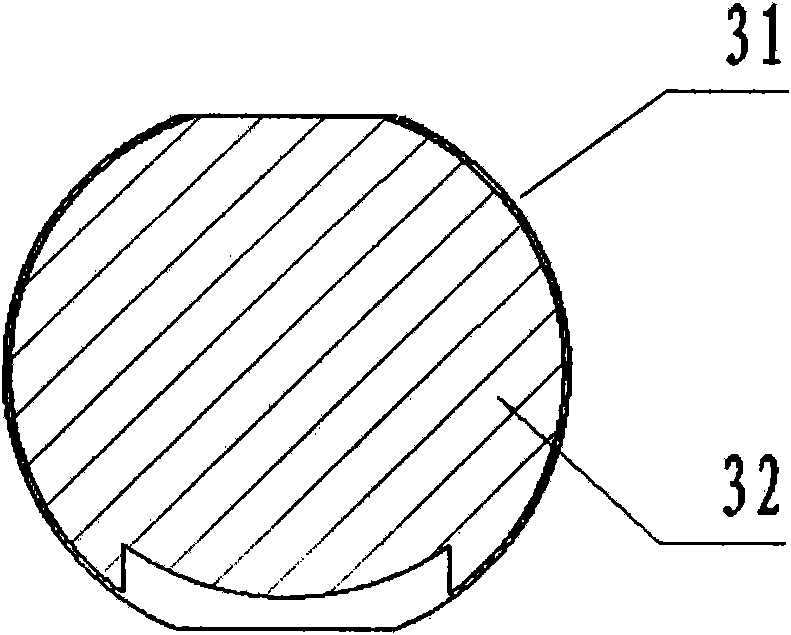
[0028] refer to figure 1 Shown is the front view of the piezoelectric sheet of the present invention. Surface electrodes 32 are arranged on the piezoelectric sheet 31 in this embodiment. The piezoelectric sheet 31 has an arched structure, and two arcs are symmetricall...


PUM


Abstract

The invention discloses a piezoelectric transformer with an arch structure, in particular a novel sandwich type multi-drive and multi-output piezoelectric transformer. The piezoelectric transformer comprises drive end piezoelectric patches and output end piezoelectric patches which work in a transverse vibration mode; the piezoelectric transformer is formed by overlaying the drive end piezoelectric patches and the output end piezoelectric patches; and at least one part of the drive end piezoelectric patches or the output end piezoelectric patches has an arch structure. Unlike the prior art, the piezoelectric transformer consists of the arc piezoelectric patches which facilitate the welding of electrodes and the positioning and improve the firmness and reliability. The upper and lower surfaces of each piezoelectric patch are coated with metal plane electrodes; and the sides of the arch shape are covered with side electrodes which are connected with the surface electrodes respectively, and are polarized in the thickness direction. Outer conducting wires are directly led out through the side electrodes; and all layers of the piezoelectric patches are connected in parallel, so the structure is simple and reasonable.

Description

technical field [0001] The invention relates to a transformer, in particular to a piezoelectric transformer, which can be widely used in fluorescent lamp ballasts, adapters, piezoelectric power supplies and the like. Background technique [0002] The trend of miniaturization and integration of modern power electronic systems makes the disadvantages of traditional magnetic components obvious, and the current research work on piezoelectric transformers as a substitute for magnetic transformers has made great progress. Compared with the electromagnetic transformers widely used at present, the piezoelectric transformer has the characteristics of non-flammability, no electromagnetic radiation, small size, simple structure and high conversion efficiency. In order to realize miniaturization and thinning of electronic circuits, piezoelectric transformers are suitable for use in circuits such as inverters for liquid crystal panels and DC / DC converters. Piezoelectric transformers use...

Claims


Application Information

Patent Timeline
Patent Type & Authority Applications(China)
IPC IPC(8): H01L41/107H10N30/40
Inventor 周伟革都金龙武彬
Owner 北京为华新光电子有限公司
Learn More