Pressing wheel assembly for connecting pipes

A technology of pipe connection and pressure wheel, which is applied in the direction of pipe/pipe joint/pipe fitting, flange connection, sleeve/socket connection, etc., which can solve the problem of cumbersome assembly work and so on.

Inactive Publication Date: 2012-06-20
HYUNDAI CASTIRON PROD
0 Cites 0 Cited by

AI-Extracted Technical Summary

Problems solved by technology

Therefore, the assembly w...

Method used

In the pressure wheel assembly for pipe connection of the present invention assembled as described above, as shown in FIG. 7 , even if the length of the connecting pipe 90 is reduced due to the low temperature in winter, or the abnormal high pressure inside the pipe is Make the connecting pipe 90 move in the direction of the arrow 95 in the receiving pipe 70, and the pressure roller 10 can also be firmly assembled to the receiving pipe 70 through the connecting bolt 60, so there is no need to worry about the distance between the pressure roller 10 and the receiving pipe 70 changing. Moreover, as long as the pressure roller 10 does not fall off, the inner wheel portion 11 of t...

Abstract

A pressing wheel assembly for connecting pipes is provided to accomplish assembly conveniently by fastening a support ring on a pressing wheel with a stopper and a spike rest on the pressing wheel. A pressing wheel assembly for connecting pipes comprises a pressing wheel(10). The pressing wheel comprises a horizontal part(13) connecting the upper ends of an inner wheel part(11) and an outer wheelpart(12); a mounting groove(14) formed on the top of the inner ring part and a leg hole(15); a bolt hole(16) formed on the horizontal part; and a bolt mounting part(17) formed in the outer wheel part. A ring part(21) of a stopper(20) and leg parts(22) are mounted to the mounting groove. The leg parts of the stopper are protruded into the wheel part. A spike(30) is fitted into a hollow part(42) ofa support ring(40). A flange part(44) of the support ring is held in the horizontal part with a bolt(51) and a nut(52).

Application Domain

Sleeve/socket jointsFlanged joints

Technology Topic

EngineeringFlange

Image

  • Pressing wheel assembly for connecting pipes
  • Pressing wheel assembly for connecting pipes
  • Pressing wheel assembly for connecting pipes

Examples

  • Experimental program(1)

Example Embodiment

[0016] Hereinafter, the preferred embodiments of the present invention will be described in detail with reference to the accompanying drawings.
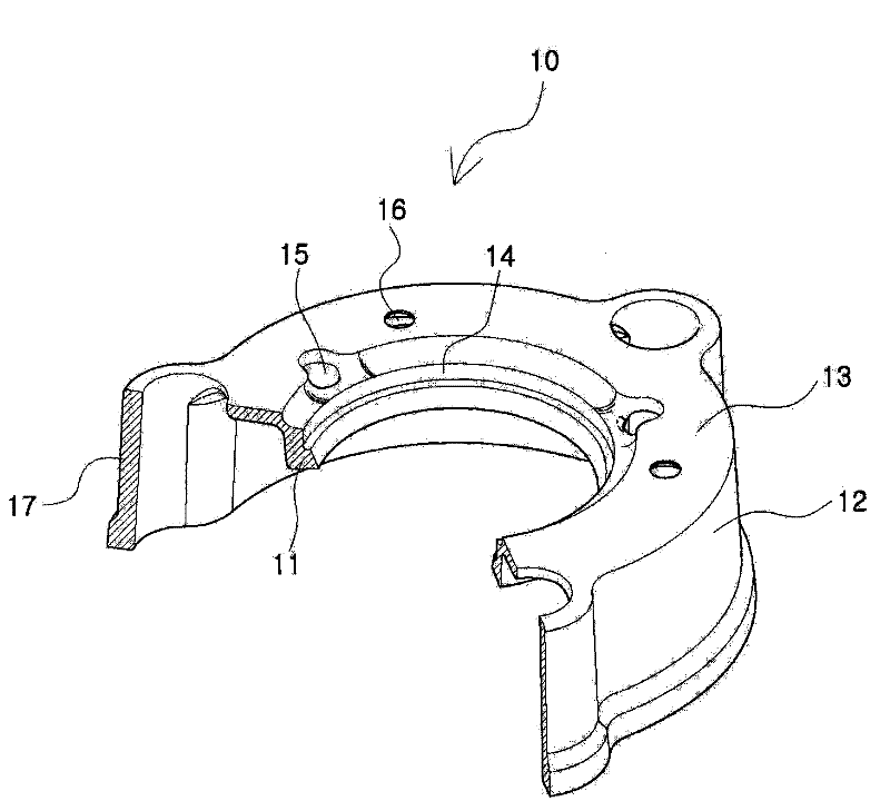
[0017] In order to explain the assembling structure of the pressure roller assembly for pipe connection of the present invention, firstly the combination figure 2 The structure of the pinch roller will be described in detail.
[0018] like figure 2 As shown, the pressure roller 10 of the pipe connection pressure roller assembly of the present invention includes an inner wheel portion 11, an outer wheel portion 12, and a horizontal portion 13; wherein, the upper end of the inner wheel portion 11 and the upper end of the outer wheel portion 12 pass through the The horizontal portion 13 is connected; the upper end of the inner wheel portion 11 is formed with a mounting groove 14 and a leg hole 15 ; the horizontal portion 13 is formed with a bolt hole 16 ; the outer wheel portion 12 is formed with a bolt mounting portion 17 .
[0019] On the pinch roller of the above structure, the other parts of the pinch roller assembly for pipe connection are mounted as follows to form an assembled body unit.
[0020] like image 3 and Figure 4 As shown, the pressure roller assembly for pipe connection of the present invention further includes a brake 20, a toothed nail 30, a support ring 40, and a connecting bolt 60; wherein, the brake 20 includes a ring portion 21 and a leg portion 22, the ring portion 21 and The legs 22 are respectively installed in the mounting grooves 14 and the leg holes 15 of the pressing wheel 10 , so that the legs 22 of the brake 20 protrude from the inside of the pressing wheel 10 ; 21, and the toothed nails 30 are inserted into the hollow portion 42 of the cylindrical portion 41 formed in the support ring 40; The horizontal part 13; the connecting bolt 60 is installed on the bolt installation part 17 of the pressure roller 10 through the nut 61.
[0021] The lower end of the inner wheel portion 11 of the pressing wheel 10 protrudes to the inside, and the lower end of the inner wheel portion 11 is used to press the receiving pipe 70 (please refer to Figure 5 ) of the closed loop 80 (please refer to Figure 5 ) of the pressurized ring, and, in figure 2 and image 3 Although only three bolt mounting portions 17 and bolt holes 16 are shown respectively, the number of the bolt mounting portions 17 and the bolt holes 16 can be adjusted according to the size of the pressing roller.
[0022] A plurality of the leg portions 22 are formed on the ring portion 21 of the stopper 20 . exist figure 2 and image 3 , although only three legs 22 are shown, their number can be adjusted according to the size of the pressing roller.
[0023] The tooth nails 30 are connected to form a ring by a plurality of pieces 31 and elastic bodies 34 arranged alternately with each other. The inner side of the block 31 is formed with a side claw 32, and the outer side is formed with an inclined portion 33 . According to the above structure, even if the connecting pipe 90 clamped by the tine 30 (please refer to Figure 5 ) into an oval shape due to external force, the toothed nails 30 can also clamp the connecting pipe 90 with a uniform force.
[0024] The elastic body 34 may be made of rubber or elastic synthetic resin, and may have the same side profile as that of the block piece 31 .
[0025] The support ring 40 is formed by inserting the teeth 30 into the hollow portion 42 to form a cylindrical portion 41 with a certain height h; in order to prevent the combination of the bolts 51 and the connecting bolts 60 from interfering with each other, the outer peripheral surface of the cylindrical portion 41 A groove 43 is formed on it; a flange 44 is formed at the lower end of the cylindrical portion 41 ; a bolt hole 45 for inserting the bolt 51 and a bolt hole 45 for inserting the bolt 51 are formed at the position corresponding to the groove 43 on the flange 44 The bolt mounting portion 46 of the bolt 60; the bolt mounting portion 46 is arranged in a shape aligned with the bolt mounting portion 17 of the pinch roller 10; an inclined surface 47 is formed around the hollow portion 42; the inner lower end of the cylindrical portion 41 Leg grooves 48 are formed.
[0026] In the pinch roller assembly for pipe connection of the present invention having the above-mentioned structure, since the pinch roller 10 does not need to be turned over for assembly, the support ring 40 can be fixed to the pinch roller 10 in a state where the brake 20 and the tine 30 are mounted on the pinch roller 10 . Therefore, during the assembly process, it is easy to locate the installation position of the brake 20 and the toothed nail 30, so that the brake 20 and the toothed nail 30 are not easily separated from the installation position, so as to facilitate the assembly, and can be assembled in the factory after the assembly is completed. Transported to the job site for easy use on the job site.
[0027] Below, combine Figure 5 and Image 6 A process for connecting two pipes using the pinch roller assembly for pipe connection of the present invention assembled by the above-mentioned process will be described.
[0028] (A) The sealing ring 80 is attached to the inclined portion of the receiving pipe 70 .
[0029] (B) The pinch roller assembly 100 for pipe connection of the present invention is inserted into the connection pipe 90 .
[0030] (C) Insert the front end of the connecting pipe 90 into the sealing ring 80 attached to the receiving pipe 70 .
[0031] (D) After pulling the pressure roller assembly 100 for pipe connection of the present invention into which the connecting pipe 90 is inserted, close to the receiving pipe 70, hook the hooking part of the lower end of the connecting bolt 60 to the lower end of the flange 73 of the receiving pipe 70, A nut 61 is then coupled to the connecting bolt 60 .
[0032] After (E), the nut 61 is tightened to complete the assembly. At this time, if Image 6 As shown, due to the action of the connecting bolt 60, the pressure roller 10 will move to the side of the receiving pipe 70, the legs 22 of the brake 20 will be inserted into the leg grooves 48 of the support ring 40, and the brake 20 will push up the teeth 30. , so that the teeth 30 are clamped by the inclined surface 47 of the support ring 40 to clamp the connecting pipe 90 . In addition, the lower end of the inner wheel portion 11 of the pinch roller 10 presses the sealing ring 80, and the sealing ring 80 seals the gap between the receiving pipe 70 and the connecting pipe 90, and when the leg 22 of the brake 20 stops at the leg of the supporting ring 40 When the groove 48 is formed, the leg portion 22 of the stopper 20 is supported by the flange 73 of the receiving pipe 70, so when the nut 61 is tightened, the pressure roller 10 can be prevented from moving too far to the receiving pipe 70 side, thereby preventing the The inner wheel portion 11 of the pressing wheel 10 pushes down the sealing ring 80 too much.
[0033] In the pinch roller assembly for pipe connection of the present invention assembled as described above, such as Figure 7As shown, even if the length of the connecting pipe 90 is shortened due to the extremely low temperature in winter, or the connecting pipe 90 is moved in the direction of the arrow 95 in the receiving pipe 70 due to abnormal high pressure inside the pipe, the pressure roller 10 can be connected by The bolt 60 is firmly assembled to the receiving pipe 70, so there is no need to worry about the distance between the pressure roller 10 and the receiving pipe 70 changing. Moreover, as long as the pressure roller 10 does not fall off, the inner wheel portion 11 of the pressure roller 10 can continue to be pressed and sealed. Therefore, even if the connecting pipe 90 moves, the sealing function of the sealing ring 80 is not affected. In addition, since the teeth 30 that clamp the connecting pipe 90 are contracted by the inclined surface 47 of the support ring 40, the backward movement of the connecting pipe 90 can be suppressed to the maximum extent, and the bolt mounting part of the support ring 40 is aligned with the bolt mounting part of the support ring 40. 46 and the bolt mounting portion 17 of the pressure roller 10 , the connection between the support ring 40 and the pressure roller 10 is strengthened by the connecting bolt 60 and the nut 61 , so that the support ring 40 can be prevented from being loosened from the pressure roller 10 .

PUM

no PUM

Description & Claims & Application Information

We can also present the details of the Description, Claims and Application information to help users get a comprehensive understanding of the technical details of the patent, such as background art, summary of invention, brief description of drawings, description of embodiments, and other original content. On the other hand, users can also determine the specific scope of protection of the technology through the list of claims; as well as understand the changes in the life cycle of the technology with the presentation of the patent timeline. Login to view more.
Why Eureka
Try Eureka