
Self-generating resiliometer

A rebound hammer, self-generating technology, applied in current collectors, electric vehicles, electrical components, etc., can solve the problems of high cost, constant use, complex structure, etc., and achieve the effect of low-power circuits

Inactive Publication Date: 2010-09-22
李沛樯
View PDF5 Cites 0 Cited by
  • Summary
  • Abstract
  • Description
  • Claims
  • Application Information

AI Technical Summary

Problems solved by technology

[0006] The purpose of the present invention is to provide a self-generating rebound rebounder to overcome the defects of complex structure, unchanged use and high cost in the existing electronic rebound rebounder.

Method used


Image

  • Self-generating resiliometer
  • Self-generating resiliometer
  • Self-generating resiliometer

Examples


Embodiment Construction

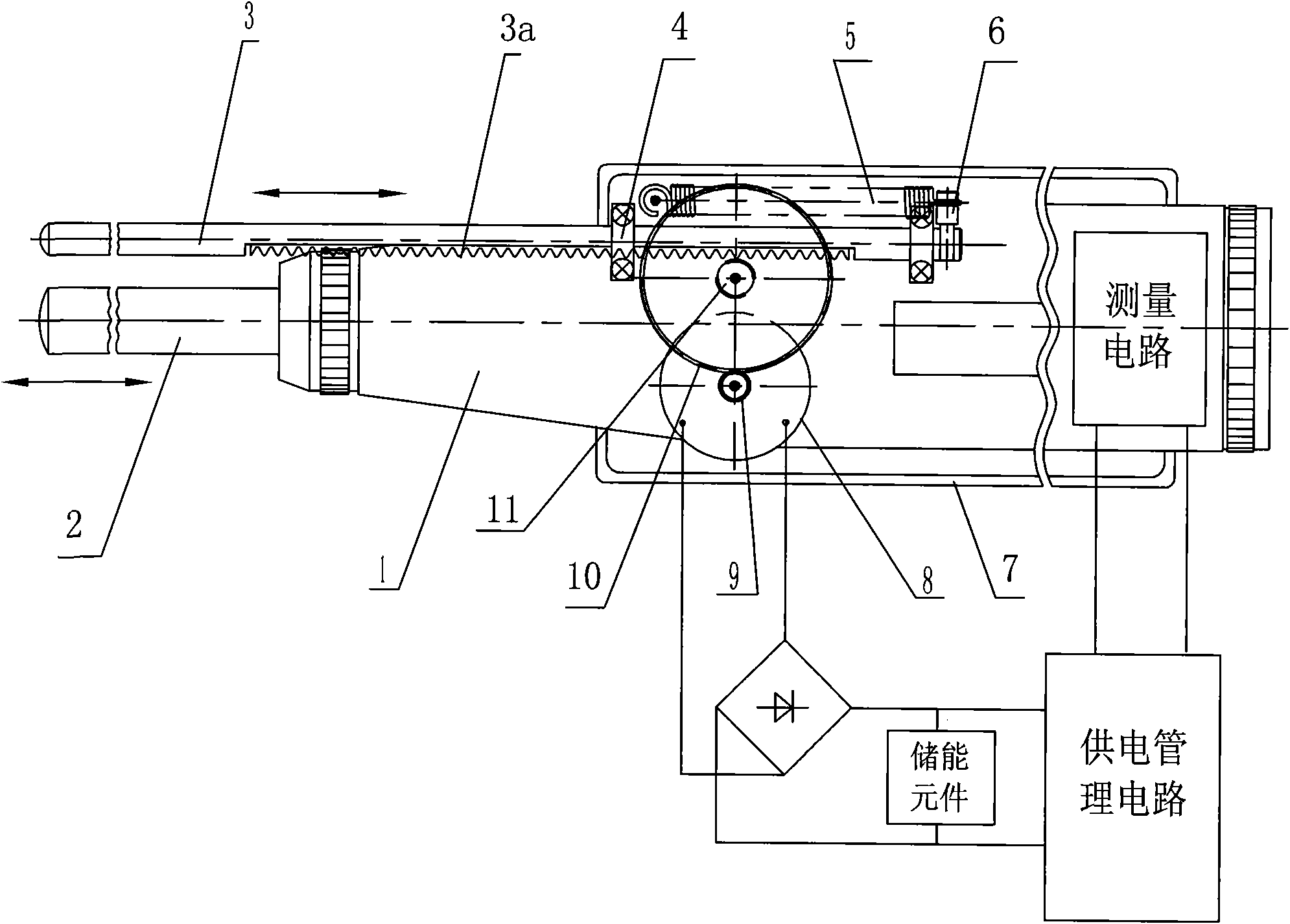
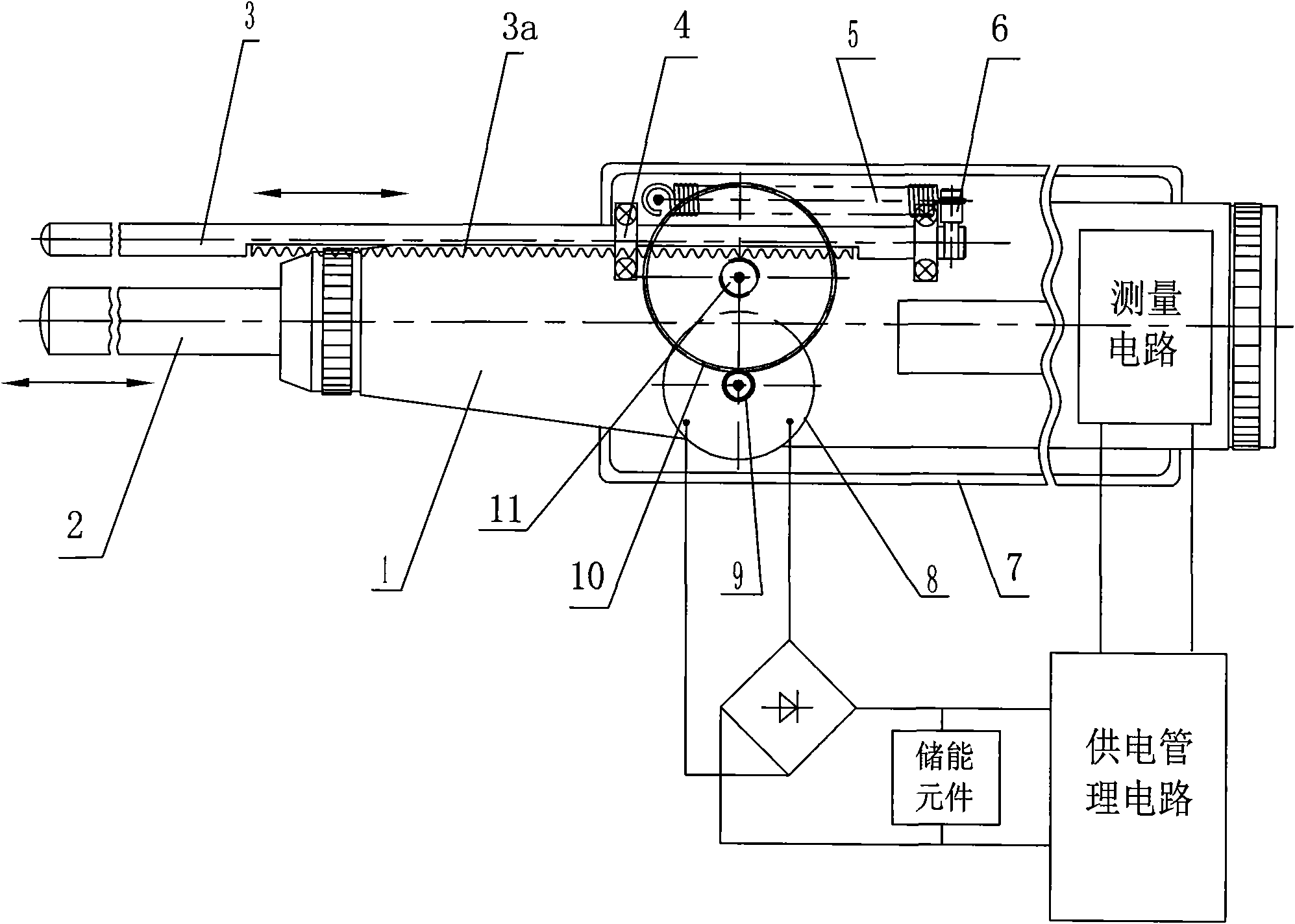
[0026] Such as figure 1 As shown, a kind of self-generating rebound hammer provided by the present invention includes rebound hammer 1 and its measuring circuit, and the innovative part of the present invention lies in:

[0027] a. Two guide rail brackets 4 and a spring 5 are arranged on the rebound hammer 1, and a slidingly fitted guide rod 3 is arranged in the guide rail bracket 4, and a section of rack 3a is arranged on one side of the guide rod 3, and the guide rod 3 extends back The part of the hammer 1 is substantially flush with the end of the hammer 2, the left end of the spring 5 is fixedly connected to the housing of the hammer 1, and the right end is connected to the right end of the guide rod 3.

[0028] B, a gear set consisting of a pinion 11 and a bull gear 10 is set in the rebound hammer 1, and a micro-generator 8, the pinion 11 in the gear set and the rack 3a on the guide rod 3 form a meshing transmission, The bull gear 10 in the gear set is engaged with the p...


PUM


Abstract

The invention relates to a self-generating resiliometer, which is characterized in that: (a) a guide rail bracket (4) and a spring (5) are arranged on a resiliometer (1), a guide rod (3) with a rack (3a) is arranged in the guide rail bracket (4), the left end of the spring (5) is fixedly connected to a resiliometer shell and the right end of the spring (5) is connected to the guide rod (3); (b) a pinion (11) and a large gear (10) are arranged in the resiliometer (1), the pinion (11) is in meshing transmission with the rack (3a), and the large gear (10) is in meshing transmission with a pinion (9) connected on an output shaft of a generator (8) and drives the generator to generate electricity; and (c) a bridge rectifier circuit, an energy storage element and a power supply management circuit are arranged in the resiliometer and the power supply management circuit is connected with the measuring circuit. Compared with the prior art, the self-generating resiliometer has the advantages of (1) having stored energy without being connected with a commercial power, (2) having self-generating function without being charged frequently, and (3) adopting a low power consumption circuit, being free from maintenance for a long time and the like.

Description

technical field [0001] The invention relates to a geotechnical measuring device, in particular to a rebound hammer for measuring the compressive strength of concrete. Background technique [0002] The concrete rebound tester uses a spring to drive the hammer and the restoring force of the instantaneous elastic deformation generated by the bullet rod hitting the concrete surface, so that the hammer drives the marking slider to bounce back and indicates the distance of the bounce. The rebound value (the ratio of the rebound distance to the distance between the bouncing hammer and the bouncing rod before the impact, calculated as a percentage) is used as one of the indicators related to the compressive strength of concrete to estimate the compressive strength of concrete. The rebound value actually reflects the surface hardness of the concrete. [0003] There are two types of existing rebound hammers: mechanical type and electronic type. The mechanical type rebound hammer requ...

Claims


Application Information

Patent Timeline
Patent Type & Authority Applications(China)
IPC IPC(8): G01N3/52H02J7/18
Inventor 李沛樯李新义
Owner 李沛樯
Learn More