
Current measurement device

A current measuring device, a technology of sourcing current, applied in the direction of measuring device, measuring electrical variable, measuring current/voltage, etc., can solve the problems of open circuit of measuring circuit and inconvenient use, and achieve the improvement of measuring accuracy, simple control method, and solution to switching Modulation effect

Active Publication Date: 2010-09-22
RIGOL
View PDF5 Cites 26 Cited by
  • Summary
  • Abstract
  • Description
  • Claims
  • Application Information

AI Technical Summary

Problems solved by technology

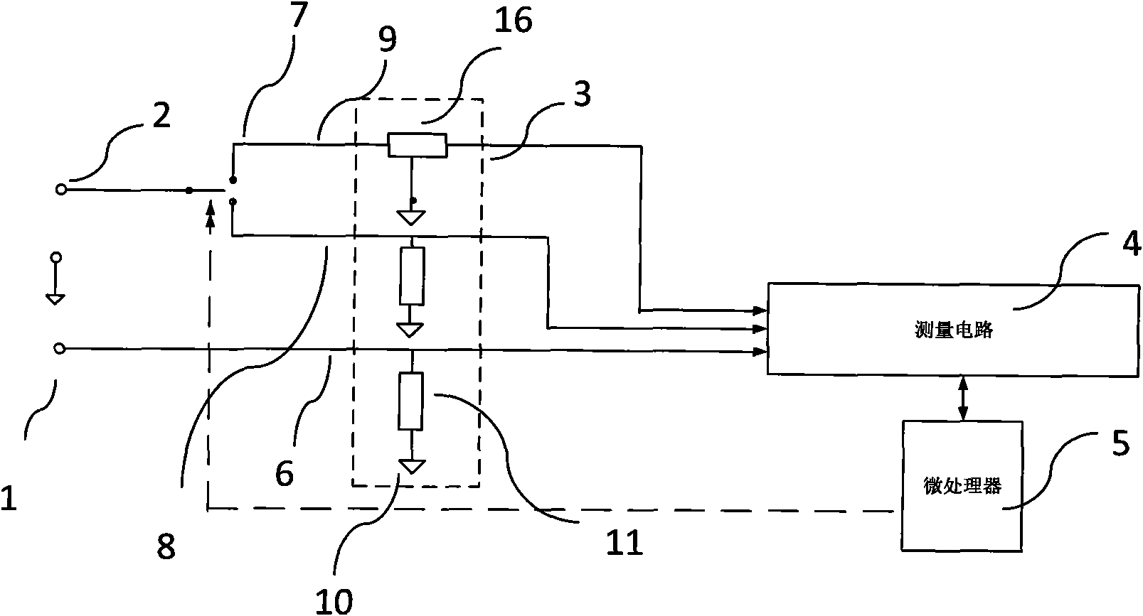
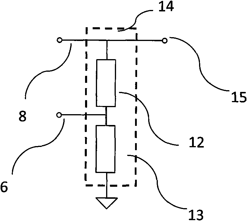
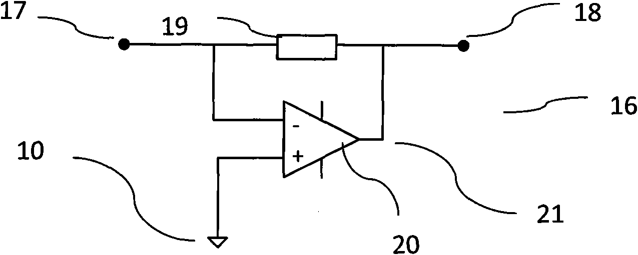
[0026] In order to solve the problem of inconvenient use caused by the use of two different lead-in terminals for large current measurement and small current measurement in current measurement, and to solve the problem that the switching circuit is easy to cause instantaneous disconnection of the measurement circuit, the present invention provides a different Compared with the current measuring device of the prior art

Method used


Image

  • Current measurement device
  • Current measurement device
  • Current measurement device

Examples


Embodiment Construction

[0092] In order to further illustrate a current measuring device of the present invention, the first embodiment selected by the present invention will be described below with reference to the accompanying drawings.

[0093] In the first embodiment of the present invention, the current measuring device is a digital multimeter.

[0094] The digital multimeter has a current input terminal 201, a switch circuit 202, a sampling circuit 203, a measurement circuit 204, and a control circuit 205. Refer to Figure 6 .

[0095] Wherein, the switch circuit 202 is composed of a first switch 206 and a second switch 207 .

[0096] The sampling circuit 203 is composed of two resistors 210 and 211 connected in series between the output terminal 208 and the common terminal 209 of the sampling circuit 203 in sequence, wherein the middle connection point of the resistor 210 and the resistor 211 constitutes the first current of the sampling circuit 203 The sampling terminal 212 and the output ter...


PUM


Abstract

The invention relates to a current measurement device, in particular to a DC current measurement device, which comprises a leading-in end 251, a control part 255, a switch part 252, a sampling part 253 and a measuring part 254. The sampling part 253 is provided with a sampling end 262, a sampling end 263 and a sampling end 280, the switch part 252 comprises a switch 282 for controlling the connection or disconnection of a circuit between the leading-in end 251 and the sampling end 262 and a switch 283 which is used for ensuring the connection between the leading-in end 251 and the sampling end 263 or the sampling end 280. The sampling part 253 comprises a current-voltage transforming circuit 265 between the sampling end 280 and the measuring part 254, and the current-voltage transforming circuit 265 is controlled by the control part 255 to be connected or disconnected. When the switch 282, 283 or 276 changes, the leading-in end 251 of the current measurement device is free from the instantaneous circuit break phenomenon, so the measured circuit can be effectively protected; and moreover, the control method is simple, and the work is stable.

Description

technical field [0001] A current measuring device of the present invention relates to the field of electric variable measurement, in particular to the field of current measurement. Background technique [0002] In the prior art, many measuring devices have current measurement capabilities, such as ammeters and multimeters, and some oscilloscopes and test systems also have current measurement capabilities. [0003] Among them, the most commonly used current measurement circuit has two current measurement terminals 1, 2, a sampling circuit 3, a measurement circuit 4, and a control circuit 5, wherein the current measurement terminals 1 and 2 are used for large current measurement and small current measurement respectively, such as figure 1 As shown, taking DC current measurement as an example, the measurement range of large current usually refers to the range of 200mA-10A, and the measurement range of small current usually refers to the range of less than or equal to 200mA. ...

Claims


Application Information

Patent Timeline
Patent Type & Authority Applications(China)
IPC IPC(8): G01R19/00G01R15/09
Inventor 王悦王铁军李维森
Owner RIGOL
Learn More