
e for mosfet 2 Resonance-like driving circuit and its modulation method

A driving circuit and resonant inductor technology, applied in the field of high-frequency switching power supply, can solve the problems of inability to realize ON-OFF modulation, misleading switching devices, and slow start-up process of the drive circuit, so as to avoid the slow start-up process and avoid Easily misleading turn-on, reliable negative pressure turn-off effect

Active Publication Date: 2022-04-05
XIAN UNIV OF TECH
View PDF7 Cites 0 Cited by
  • Summary
  • Abstract
  • Description
  • Claims
  • Application Information

AI Technical Summary

Problems solved by technology

However, this type of scheme cannot realize ON-OFF modulation, and can only operate in a steady state; the start-up process of the drive circuit is slow, and there may be danger of false conduction of the switching device during the start-up process, and it is impossible to realize the control of the switching device. Negative pressure shutdown of

Method used


Image

  • e for mosfet  <sub>2</sub> Resonance-like driving circuit and its modulation method
  • e for mosfet  <sub>2</sub> Resonance-like driving circuit and its modulation method
  • e for mosfet  <sub>2</sub> Resonance-like driving circuit and its modulation method

Examples


Embodiment Construction

[0020] The present invention will be described in detail below with reference to the accompanying drawings and specific embodiments.

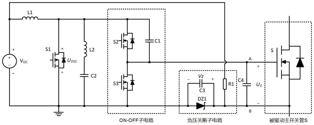
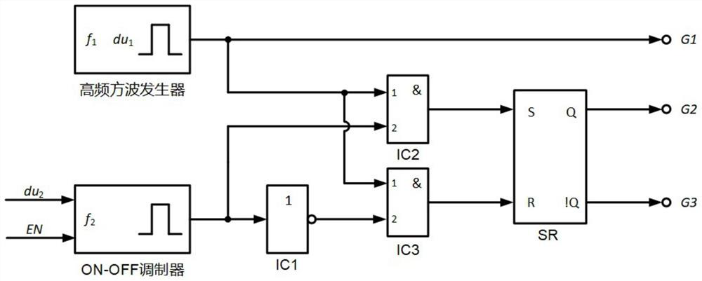
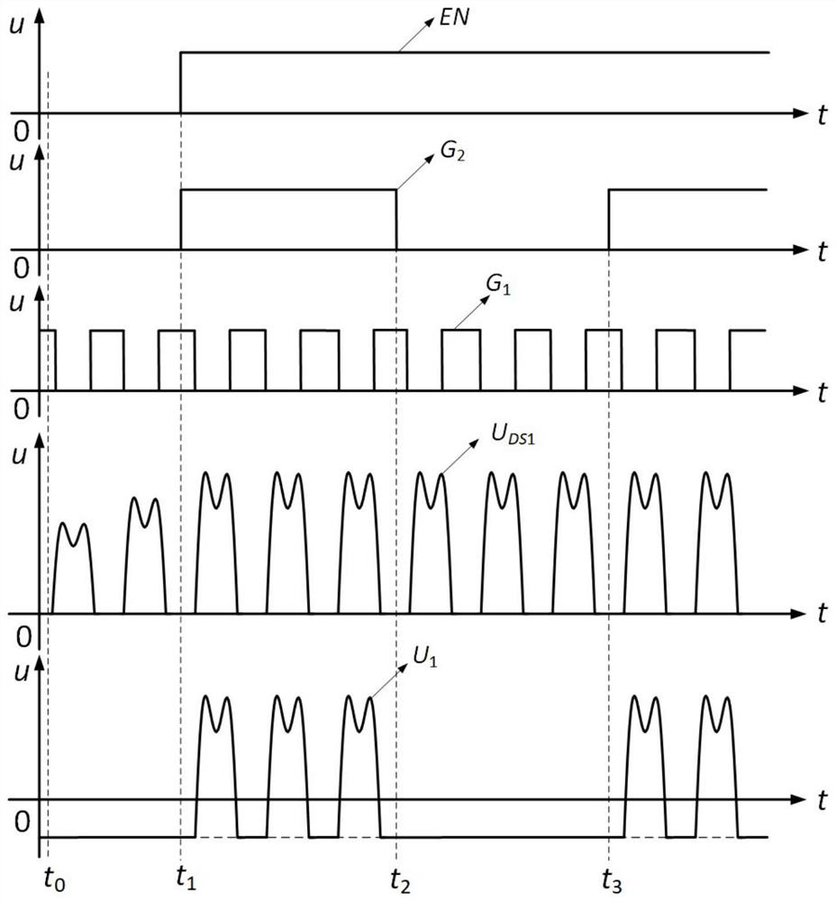
[0021] The present invention is used for E of MOSFET 2 Resonant-like driving circuit whose structure is as follows figure 1 shown, including the DC supply voltage V DC , the DC supply voltage V DC The positive pole is connected with a DC inductor L 1 one end of the DC inductor L 1 The other end of the MOSFET is connected with the first MOSFET switch S 1 drain, the first MOSFET switch S 1 The source is connected to the DC supply voltage V DC The negative pole of , also includes the double frequency resonant inductor L in series 2 and the resonant capacitor C 2 , the double frequency resonant inductor L 2 and the resonant capacitor C 2 After being connected in series, it is connected in parallel to the first MOSFET switch S 1 On the drain and source of the double frequency resonant inductor L 2 and the resonant capacitor C 2 After be...


PUM


Abstract

The invention discloses an E for MOSFET 2 The resonant drive circuit includes a DC power supply voltage, the positive pole of the DC power supply voltage is connected to one end of a DC inductance, the other end of the DC inductance is connected to the drain of the first switching tube, and the source of the first switching tube is connected to the DC power supply voltage. The negative pole also includes a double frequency resonant inductor and a resonant capacitor connected in series, the double frequency resonant inductor and the resonant capacitor are connected in series and then connected in parallel to the drain and source of the first switching tube and connected to the ON-OFF sub-circuit, DC power supply The voltage is also connected in parallel with a negative pressure shutdown sub-circuit, and the output terminals of the ON-OFF sub-circuit and the output terminal of the negative pressure shutdown sub-circuit are connected in parallel with a driven active switch tube. The invention realizes the ON-OFF driving of the high-frequency MOSFET, so that the switching device can work in the on-off mode of high-frequency resonance. The invention also discloses an E for MOSFET 2 Modulation methods for resonant-like drive circuits.

Description

technical field [0001] The invention belongs to the technical field of high-frequency switching power supplies, and relates to an E 2 A resonance-like driving circuit, and the present invention also relates to a modulation method of the above-mentioned resonance driving circuit. Background technique [0002] Metal-oxide semiconductor field effect transistors (MOSFETs) mainly include gallium nitride field effect transistors (GaNMOSFETs), silicon carbide field effect transistors (SiC MOSFETs) and silicon field effect transistors (Si MOSFETs). With the development of power electronics technology, the operating frequency of power semiconductor devices has gradually increased. In the fields of wireless power transmission, high-frequency switching power supplies, etc., the operating frequency of MOSFETs can reach up to tens of megahertz. Generally, MOSFET devices are voltage-driven devices, and the energy loss on the gate charge of the device during switching will cause a large ...

Claims


Application Information

Patent Timeline
Patent Type & Authority Patents(China)
IPC IPC(8): H02M1/08
CPCH02M1/08
Inventor 孙向东陈泽驰王之轩任碧莹
Owner XIAN UNIV OF TECH
Learn More