Full-dry high count armour indoor and outdoor optical cable

A technology with large number of cores and armored chambers, applied in the direction of fiber mechanical structure, etc., can solve problems such as construction trouble, and achieve the effect of convenient laying, easy connection and light weight

Active Publication Date: 2010-09-22
TONGDING INTERCONNECTION INFORMATION CO LTD
View PDF7 Cites 13 Cited by
  • Summary
  • Abstract
  • Description
  • Claims
  • Application Information

AI Technical Summary

Problems solved by technology

[0002] In the application of Fiber To The Home (FTTH, Fiber To The Home), the fiber optic cables between buildings mainly adopt such as figure 1 and figure 2 shown for use with fiber optic cables where, figure 1 The shown optical cable has a strengthening member 10 in its center, and a plurality of unit cables 20 are twisted and arranged on the outer periphery of the strengthening member 10, and a sheath 30 is coated on the outer periphery of the unit cables 20, and a plurality of optical fibers are arranged in each unit cable 20 201. This kind of optical cable is mainly used as an optical connection between buildings. When it is connected to the room, it needs to use figure 2 In the optical cable shown, the center of the optical cable is still a strength member 100, and two layers of tight-buffered optical fibers 200 are twisted and arranged on the periphery of the strength member 100, and finally covered by an outer sheath 300, that is to say, in FTTH applications, it is necessary to Only two types of optical cables can complete the wiring, and the construction is troublesome, and for figure 2 When the optical cable shown is used for pipeline laying, due to its soft material, it is not suitable to be laid in places with corners. At the same time, its ability to resist lateral pressure is poor, and it will affect the optical fiber when it is trampled on the road. transmission performance

Method used


Image

  • Full-dry high count armour indoor and outdoor optical cable
  • Full-dry high count armour indoor and outdoor optical cable
  • Full-dry high count armour indoor and outdoor optical cable

Examples


Embodiment Construction

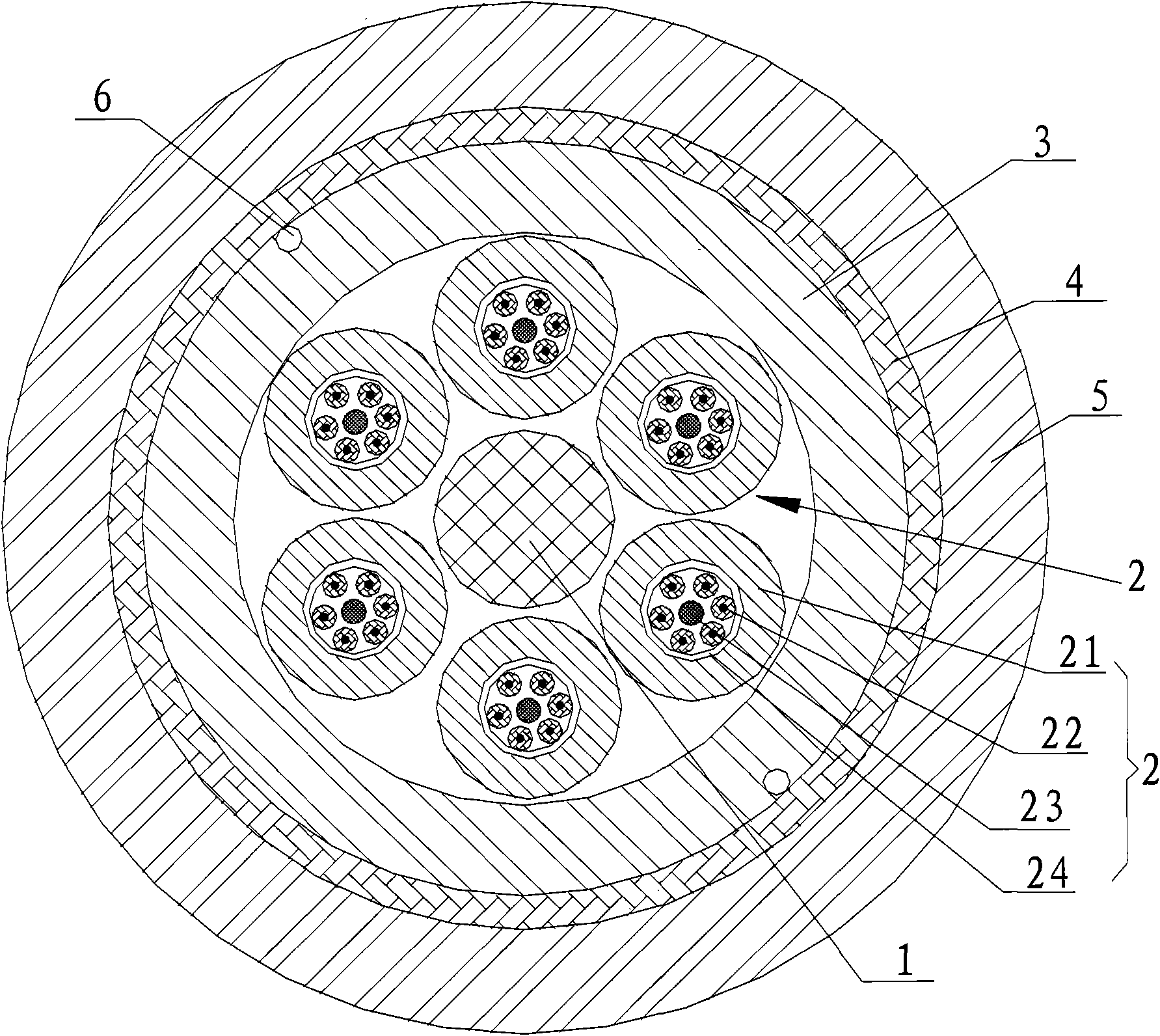
[0013] Below in conjunction with accompanying drawing, illustrate in detail the specific content of the present invention:

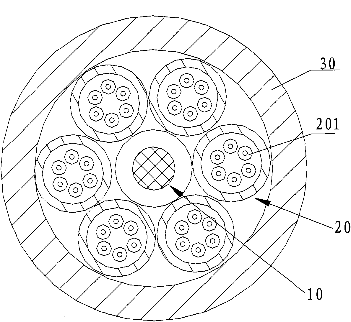
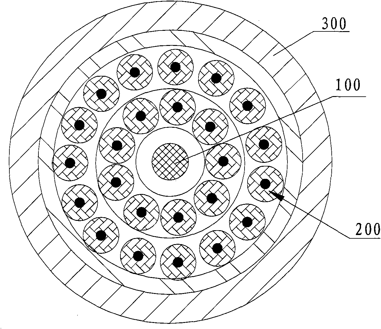
[0014] Such as image 3 The optical cable shown includes a central strengthening member 1, a plurality of unit cables 2 twisted and arranged on the outer periphery of the strengthening member 1, a PVC inner sheath 3 and a metal armor layer 4 that are sequentially covered from the inside to the outside. And the PVC outer sheath 5, wherein, each unit cable 2 comprises a loose tube 21, a plurality of tight-buffered optical fibers 22 arranged in the loose tube 21, an aramid yarn 23 that binds a plurality of tight-buffered optical fibers 22 tightly, In order to further strengthen the strength of the optical cable, a reinforcing rod 25 may also be arranged at the center of each unit cable 2 .

[0015] In this embodiment, there are six unit cables 2, and there are six tight-buffered optical fibers 22 in each unit cable 2, and the six tight-buffered optical fib...


PUM


Abstract

The invention relates to a full-dry high count armour indoor and outdoor optical cable comprising a reinforcement, a plurality of unit cables, an inner sheath, a metal armour cover and an outer sheath, wherein the reinforcement is arranged in the center, a plurality of unit cables are arranged on the periphery of the central reinforcement in a twisting mode, the inner sheath is covered on the periphery of unit cables, the metal armour cover is sheathed on the periphery of the inner sheath, the outer sheath is covered on the periphery of the metal armour cover, and each unit cable comprises a loose tube and a plurality of tight-coated fibers arranged in the loose tube. Because the optical cable of the invention is provided with the metal armour cover, the steel cable has certain side pressure proof performance, moist resistance performance and rat damage resistance and can be applied indoors and outdoors. The optical cable of the invention has small weight, does not contain liquid such as ointment and the like and is the full-dry optical cable, so that the optical cable is convenient to lay and continue.

Description

technical field [0001] The invention relates to a communication optical cable. Background technique [0002] In the application of Fiber To The Home (FTTH, Fiber To The Home), the fiber optic cables between buildings mainly adopt such as figure 1 and figure 2 shown for use with fiber optic cables where, figure 1 The shown optical cable has a strengthening member 10 in its center, and a plurality of unit cables 20 are twisted and arranged on the outer periphery of the strengthening member 10, and a sheath 30 is coated on the outer periphery of the unit cables 20, and a plurality of optical fibers are arranged in each unit cable 20 201. This kind of optical cable is mainly used as an optical connection between buildings. When it is connected to the room, it needs to use figure 2 In the optical cable shown, the center of the optical cable is still a strength member 100, and two layers of tight-buffered optical fibers 200 are twisted and arranged on the periphery of the str...

Claims


Application Information

Patent Timeline
Patent Type & Authority Applications(China)
IPC IPC(8): G02B6/44
Inventor 沈小平姜正权范荣明沈建良曹志刚钱林忠
Owner TONGDING INTERCONNECTION INFORMATION CO LTD
Why Eureka
Try Eureka