
Driving mechanism for a medium or high voltage disconnector

A control device and controlled technology, applied to the power device, mechanical equipment, transmission device, etc. inside the switch, can solve the problems of large weight and volume, restrictions, etc.

Active Publication Date: 2010-09-22
ALSTOM TECH LTD
View PDF5 Cites 17 Cited by
  • Summary
  • Abstract
  • Description
  • Claims
  • Application Information

AI Technical Summary

Problems solved by technology

[0011] However, such a device has the disadvantage of being heavy and bulky, which is necessary due to the fact that it is mounted on the transmission shaft and due to the high torques transmitted by the shaft
[0012] At present, the torque transmission ratio between the countershaft and the propshaft varies between zero and maximum in each phase of driving the propshaft in rotation, in the sense that the intermittent transmission wheel of the Malter mechanism value, which limits the possibility of providing a torque limiting device elsewhere than on said drive shaft

Method used


Image

  • Driving mechanism for a medium or high voltage disconnector
  • Driving mechanism for a medium or high voltage disconnector
  • Driving mechanism for a medium or high voltage disconnector

Examples


Embodiment Construction

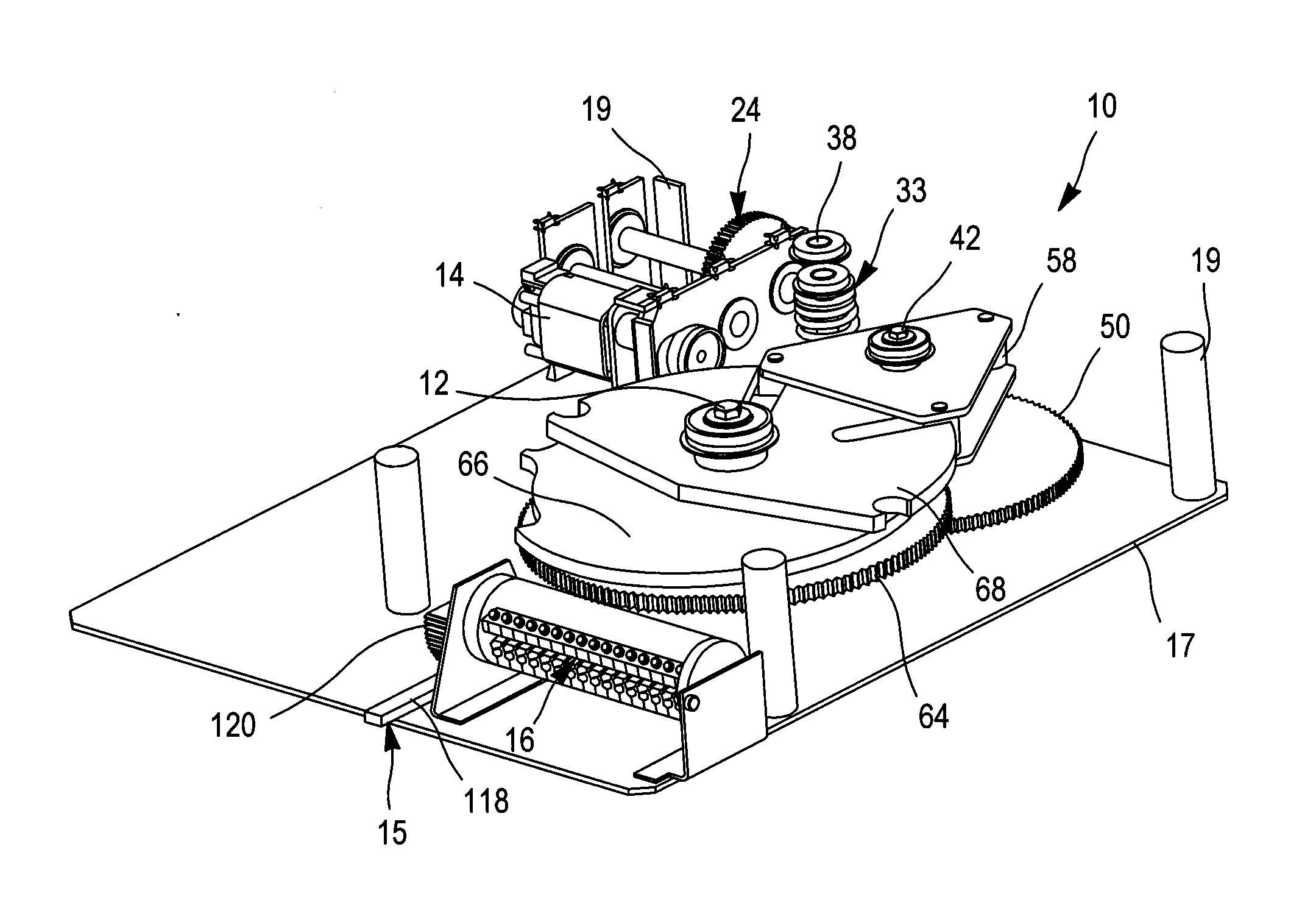
[0071] figure 1 Shown is a mechanical device 10 for controlling a circuit breaker (not shown) which is switched into a high voltage or medium voltage circuit with three switch positions.

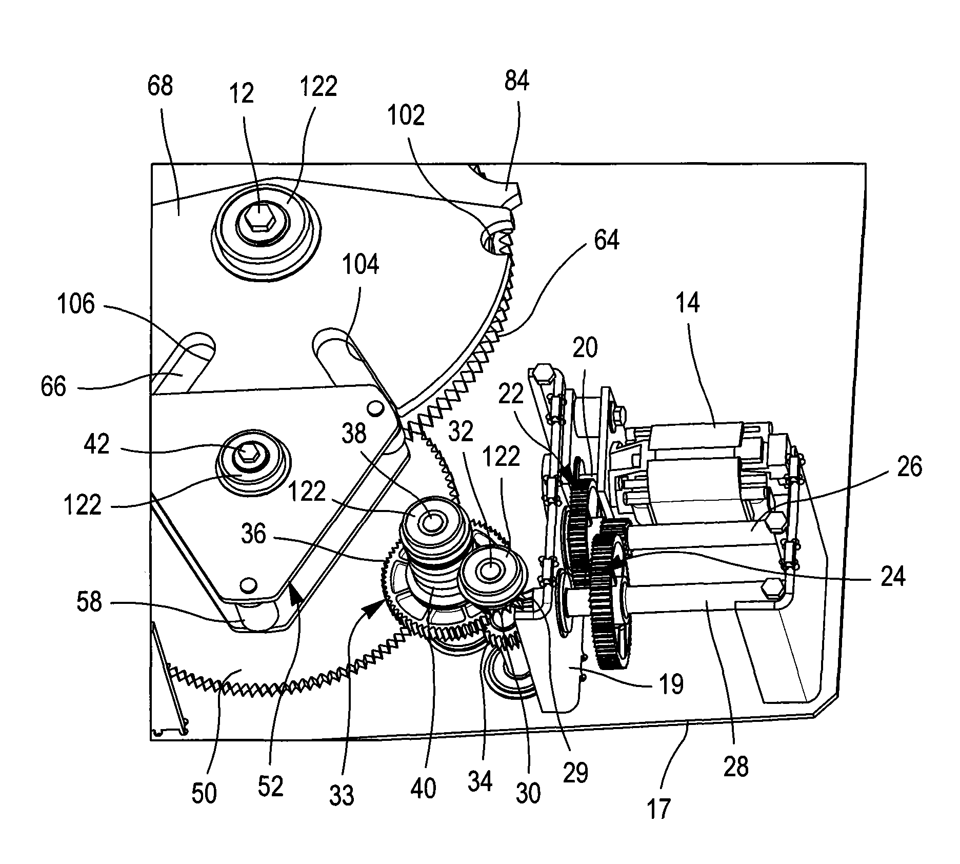
[0072] Said device 10 comprises: a transmission shaft 12 adapted to engage movable contacts of a circuit breaker of the above-mentioned type; a motor 14; means for transferring energy from said motor 14 to said transmission shaft 12; For the device 15 indicating the angular position of the transmission shaft 12 to the auxiliary switch 16, the device 15 is especially used to control the motor and send out the angular position signal of the transmission shaft 12, and the base plate 17, so The main components of the device are mounted on the base plate.

[0073] The device 10 also includes an upper base plate, which is not shown in the figure in order to reveal the internal components of the device. As will be more clearly apparent below, this upper plate is fixed to uprights 19 connected to ...


PUM


Abstract

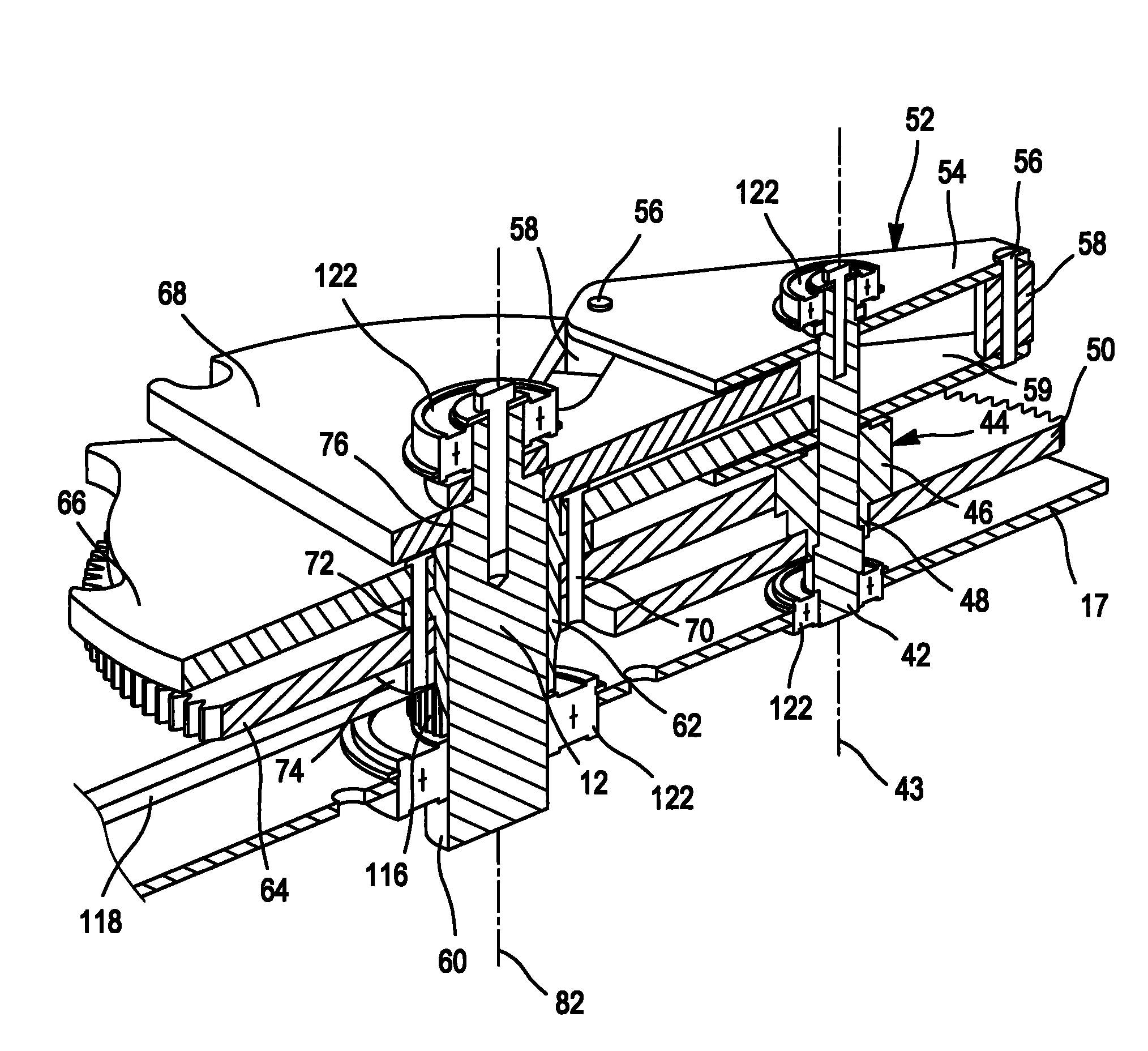
The device (10) has a driving disk (66) driven in rotation about an axis by an electric motor (14). A driven disk (68) rotates about the axis. A switching unit switches between a drive mode to drive a sleeve and a locking mode to lock an angular position of the sleeve. The unit has a rotary member carrying a cylindrical roller (58) that is simultaneously engaged in slots formed in peripheral edges of the disks due to rotation of member to induce commutation in the drive mode and disengaged from one of the slots to induce commutation in the locking mode.

Description

technical field [0001] The present invention relates to the field of mechanical control devices for electrical switchgear, in particular for high or medium voltage circuit breakers, and more generally to devices comprising a transmission shaft driven in rotation and locked in a series of discrete predetermined angular positions The drive shaft device type is in the field of mechanical control devices. [0002] High and medium voltage circuit breakers are used to disconnect a part of the live grid, such as a high voltage line, a transformer, or for example a substation, so that it can be safely accessed by workers. [0003] These circuit breakers include contactors that are movable between an open circuit position and a closed circuit position. Some circuit breakers have a dedicated grounded third position, while their contactors are also movable between said open position and said grounded position. [0004] The devices used to control circuit breakers must be very reliable ...

Claims


Application Information

Patent Timeline
Patent Type & Authority Applications(China)
IPC IPC(8): H01H3/32H01H3/52H01H9/24
CPCH01H9/16H01H31/003H01H3/44H01H3/26F16H27/06Y10T74/1418Y10T74/19005Y10T74/19879H01H33/42
Inventor 冯·爱勒曼·皮特载由盖·马丁
Owner ALSTOM TECH LTD
Learn More