
Feeding mechanism with holes punched on surface

A feeding mechanism and punching technology, applied in the field of punching feeding mechanism and surface punching feeding mechanism, can solve the problems of increasing the manufacturing cost of parts, low precision and high cost, and achieve the effect of increasing the manufacturing cost and prolonging the manufacturing cycle.

Inactive Publication Date: 2010-09-29
张光忍
View PDF0 Cites 5 Cited by
  • Summary
  • Abstract
  • Description
  • Claims
  • Application Information

AI Technical Summary

Problems solved by technology

To overcome the existing hole punching on the surface of the cone, it is necessary to design a corresponding mechanical positioning device in the mold, and the defects of complex structure, low precision, high cost and easy damage of the mold, especially in order to overcome the poor versatility of this mechanism For part replacement or part process change, the corresponding mold and corresponding device must be replaced, which aggravates the manufacturing cost of the part and prolongs the defect of the manufacturing cycle of production

Method used


Image

  • Feeding mechanism with holes punched on surface
  • Feeding mechanism with holes punched on surface

Examples


Embodiment Construction

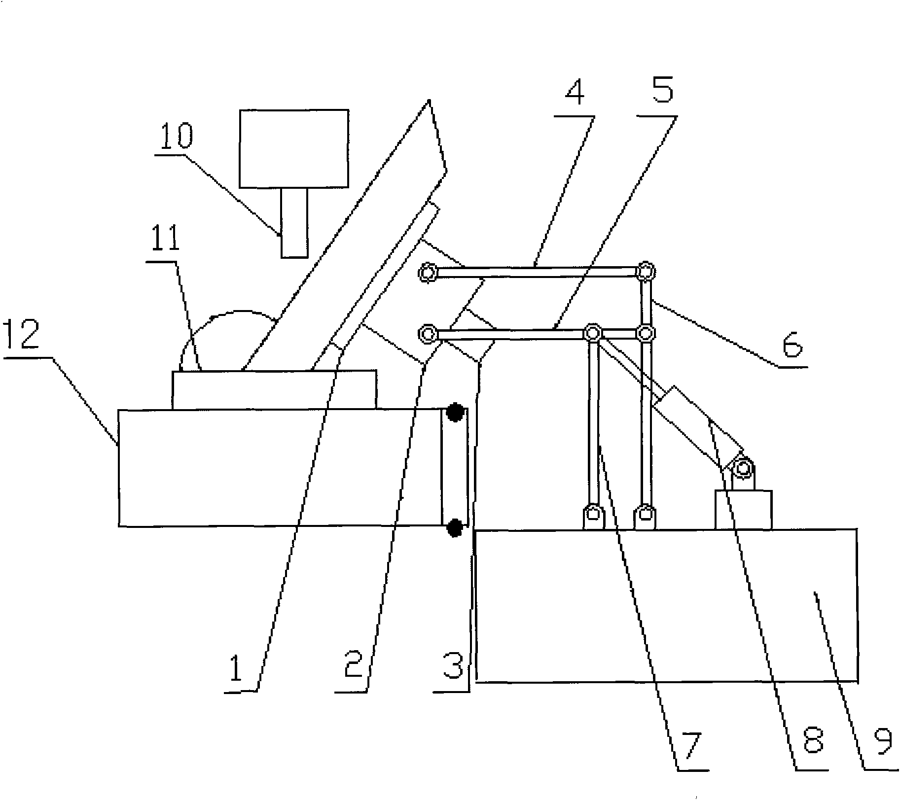
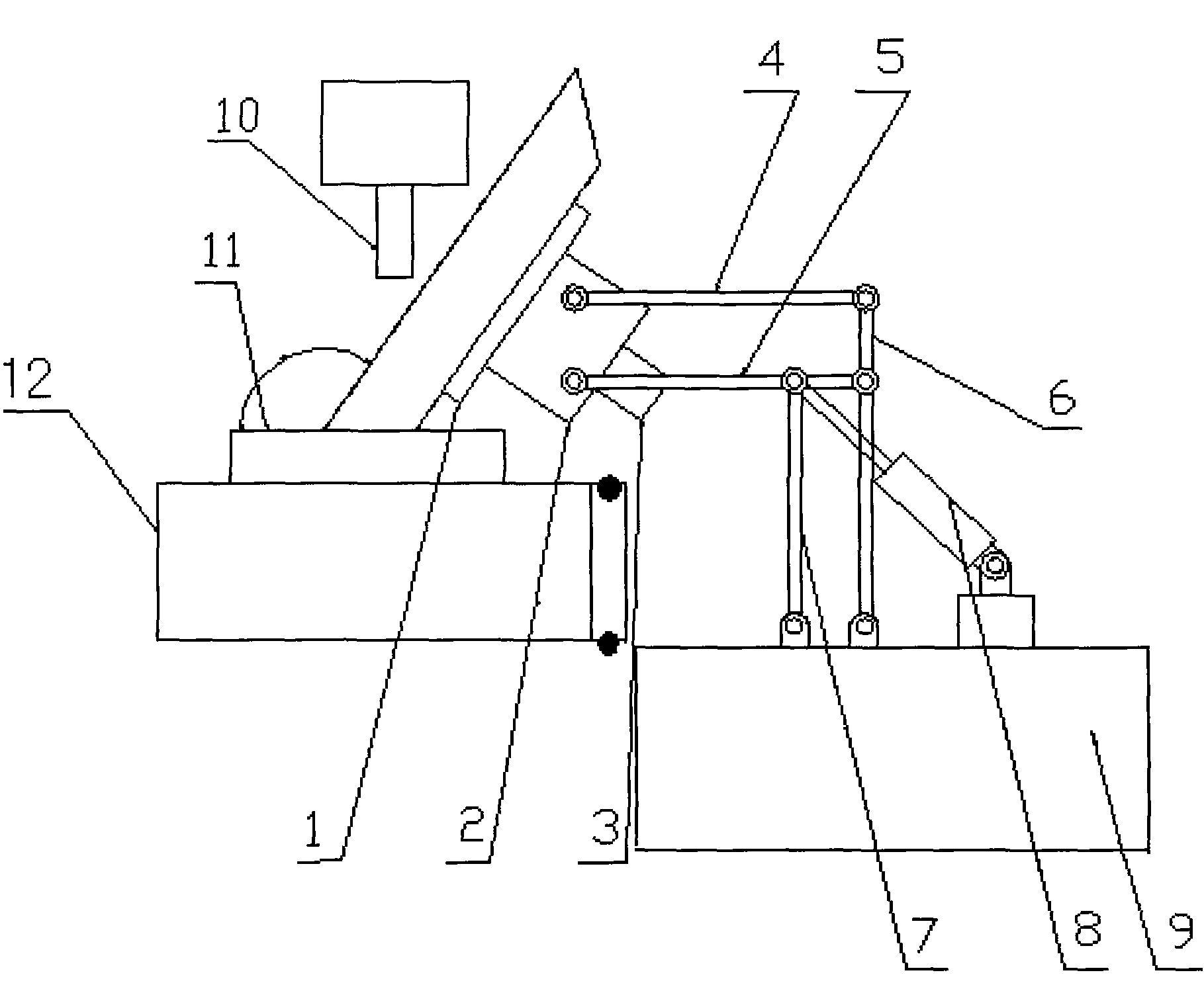
[0008] Hinge the connecting rod (4) a, connecting rod (5) b, connecting rod (6) c, and connecting rod (7) d at the corresponding positions with pins according to the correct requirements. 1), speed reducer (2), stepper motor (3) form a unified integral body hinged on one end of connecting rod (4) a, connecting rod (5) b, and connecting rod (6) c, connecting rod (7) ) d the other end is hinged on the fixed platform, the above-mentioned parts form a parallelogram luffing mechanism, and at the same time, each hinged joint is guaranteed to rotate flexibly, and finally, the piston cylinder of the cylinder (8) and the above-mentioned parts form a parallelogram luffing mechanism One of the joints in the middle is hinged, and is integrally hinged with the fixed table (9), upper mold (10), lower mold (11), and lower mold body (12), thereby realizing surface punching of various specifications.


PUM


Abstract

The invention relates to a feeding mechanism with holes punched on the surface; connecting rods (a, b, c, d) are hinged at corresponding parts by pins according to the correct requirement; simultaneously, a unified whole formed by an electromagnetic sucker, a reducing gear and a stepper motor through pins is hinged on one ends of the connecting rods (a, b); the other ends of the connecting rods (c, d) are hinged on a fixed bench; the parts form a parallelogrammic amplitude variable mechanism; simultaneously, the flexible rotation of all hinged joints is ensured; and finally, a piston cylinder of a cylinder is hinged with one hinge in the middle part of the parallelogrammic amplitude variable mechanism which is formed by the parts and is hinged with the fixed bench, an upper die, a lower die and a lower die body in an overall way so as to punch holes on the surface with different specifications.

Description

technical field [0001] The invention relates to a punching and feeding mechanism, in particular to a surface punching and feeding mechanism. It belongs to the field of stamping technology. Background technique [0002] In stamping production, parts that need to be punched on the surface of the cone are often encountered, such as the hubs of automobiles and other motor vehicles, and other similar parts, which often need to be punched on the surface of the cone. It is currently known that: Punching on the surface of the cone is realized by designing the corresponding mechanical positioning device in the mold. This kind of design of the corresponding mechanical positioning device mechanism in the mold not only has complex structure, low precision and high cost, but also is easy to be damaged due to the complex structure. , especially, this kind of mechanism is poor in versatility, and the corresponding mold and corresponding device must be replaced when the part is replaced or...

Claims


Application Information

Patent Timeline
Patent Type & Authority Applications(China)
IPC IPC(8): B25J15/06B21D22/00
Inventor 张光忍
Owner 张光忍
Learn More