Eureka AIR delivers breakthrough ideas for toughest innovation challenges, trusted by R&D personnel around the world.

Liquid injection automatic control valve

A technology for automatic control of valves and liquids, applied in the direction of fluid distribution valves, valve details, valve devices, etc., can solve the problems of complex maintenance, easy to be exposed to winter, manual care, etc., and achieve the effect of overcoming complex structures

Inactive Publication Date: 2011-08-17
陈玉琴
View PDF0 Cites 8 Cited by
  • Summary
  • Abstract
  • Description
  • Claims
  • Application Information

AI Technical Summary

Problems solved by technology

[0005] Commonly used solar water heater tanks are filled with water through the return pipe to give an alarm, and then the method of manually closing the water supply valve is adopted. The disadvantage is that the installation is complicated, two water pipes are required, and the maintenance is complicated. Manual care is required when filling the water, which is time-consuming and laborious. If you don't pay attention, it will cause water leakage and other accidents. Secondly, the junction of the pipeline and the water tank is prone to winter in winter, causing troubles that the water will not go up and down.
[0006] Existing automatic control valves for water filling of solar water heater tanks, one requires power supply, one requires dual water passages in and out, and the other requires an additional water bucket with a volume of about three liters. The common feature is that the structure is complex, expensive, and easily damaged. , basically no promotion value

Method used


Image

  • Liquid injection automatic control valve
  • Liquid injection automatic control valve

Examples


Embodiment Construction

[0019] The specific implementation of the liquid filling automatic control valve of the present invention will be described below with reference to the accompanying drawings.

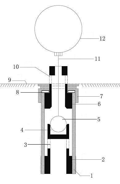
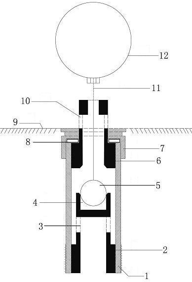
[0020] Such as figure 1 As shown, the liquid filling automatic control valve of the present invention includes a valve body 1, a valve front seat 2, a valve front seat cross flow hole 3, a valve chamber 4, a valve ball 5, a valve back seat 6, a valve connecting cap 7, a leak-proof pad 8, For those skilled in the art, it is obvious to those skilled in the art that the cross flow hole 10 in the back seat of the valve, the valve stem 11 and the float 12 have a design value of the maximum buoyancy of the float 12 greater than the total weight of the float 12, the valve ball 5 and the valve stem 11.

[0021] When the liquid filling automatic control valve of the present invention is connected with the casing, the control valve is fixed on the bottom of the casing container 9 through the valve connection cap ...


PUM


Abstract

The invention discloses a liquid injection automatic control valve, which comprises a hollow valve body (1), a valve rear seat (6) and a valve front seat (2), wherein a valve cavity in the valve body is formed between the valve front seat and the valve rear seat; and a valve ball (5) is arranged in the valve cavity, is connected with a floating ball (12) in a box container through a valve rod (11), and can ascend and hermetically seal a ball seat at the lower end of the valve rear seat under the buoyancy action of the floating ball or can descend and fall into a valve cabin under the actions of liquid negative pressure and gravity. The valve can be widely suitable for all box containers such as an oil tank, a water tower, a water closet water tank, a solar water heater water tank and the like, can be automatically closed after injected liquid reaches a set height without the control of manpower, a lever floating ball valve and an electronic valve during liquid injection, and overcomes the defects of complex structures, high cost, high damage possibility, difficulty in maintenance and inconvenience of usage of all valves of the type in the market at present.

Description

technical field [0001] The present invention relates to a liquid control valve, in particular to an automatic control valve for liquid filling, which is used in tanks such as water towers, oil tanks, toilet water tanks, solar water heater The valve closes automatically when the liquid reaches the set position, and opens again when the liquid is released. Background technique [0002] When tanks such as oil tanks, water towers, toilet tanks, and solar water heater tanks are filled with liquid, in order to immediately close the valve and prevent liquid leakage, most of them adopt methods such as installing electronic valves, return pipes, lever float valves, and manual guards. Its structure is complicated, and the installation and maintenance costs are relatively high. [0003] Chemical and oil tanks basically adopt electronic valve control system when filling liquid, which is not only complicated in structure, but also has increased difficulty in fire prevention due to circu...

Claims


Application Information

Patent Timeline
Patent Type & Authority Applications(China)
IPC IPC(8): F16K21/18F16K31/20
Inventor 陈玉琴
Owner 陈玉琴
Why Eureka
Eureka Blog
Learn More