Brushless harmonic excitation synchronous motor

A synchronous motor and harmonic excitation technology, applied in synchronous machines, electrical components, electromechanical devices, etc., can solve the problems of permanent magnet motor dependence and expensive permanent magnet materials, and achieve the effects of good performance, convenient manufacturing and simple structure

Inactive Publication Date: 2014-06-25
HARBIN INST OF TECH
View PDF8 Cites 9 Cited by
  • Summary
  • Abstract
  • Description
  • Claims
  • Application Information

AI Technical Summary

Problems solved by technology

[0005] The present invention is to solve the problem that the existing permanent magnet motor depends on expensive permanent magnet materials, and the electric excitation motor needs an independent exciter, and now provides a brushless harmonic excitation synchronous motor

Method used


Image

  • Brushless harmonic excitation synchronous motor
  • Brushless harmonic excitation synchronous motor
  • Brushless harmonic excitation synchronous motor

Examples


specific Embodiment approach 1

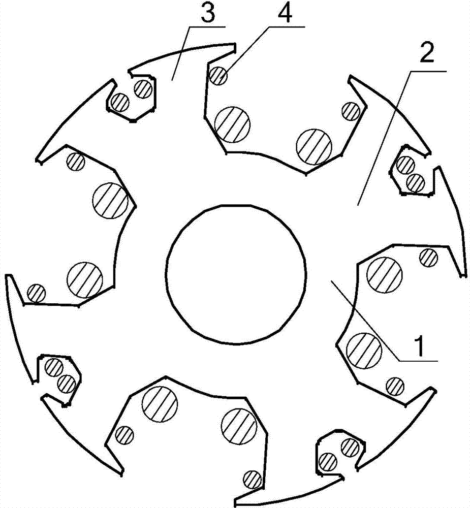
[0020] Specific implementation mode one: refer to figure 1 Specifically explain this embodiment, a brushless harmonic excitation synchronous motor described in this embodiment, the rotor core 1 of the motor has a 4-pole structure, and a winding slot is opened in the middle of the pole shoe 2 of each pole. The winding slots divide the four pole pieces into eight rotor teeth 3, and each rotor tooth 3 is nested with a harmonic winding 4.

[0021] In this embodiment, compared with the common electric excitation synchronous motor, the brushless harmonic excitation synchronous motor has a set of harmonic windings added on the rotor, and the harmonic windings can utilize the Harmonic magnetic field induces harmonic potential, and the harmonic potential provides excitation current to the excitation winding through the rotating rectifier, so as to realize brushless excitation. The motor described in this embodiment is completely based on electric excitation, does not rely on permanent...

specific Embodiment approach 2

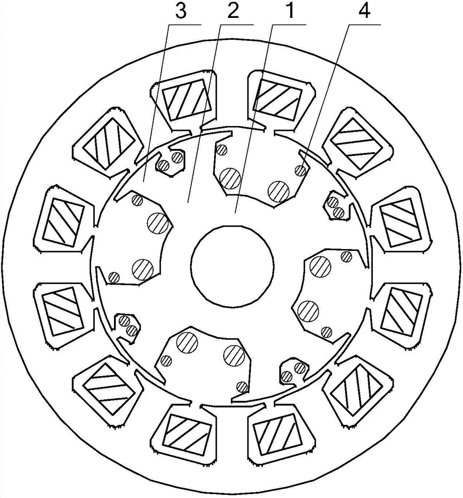
[0022] Specific implementation mode two: refer to figure 2 Describe this embodiment in detail. This embodiment is a further description of a brushless harmonic excitation synchronous motor described in Embodiment 1. In this embodiment, the stator core of the motor has a 12-slot structure, and the stator winding It is a single-layer structure with a pitch of 3 and an open winding.

specific Embodiment approach 3

[0023] Specific embodiment three: This embodiment is a further description of a brushless harmonic excitation synchronous motor described in specific embodiment one. In this embodiment, the stator core of the motor is a 12-slot structure, and the stator winding is Double-layer structure with a pitch of 3.

[0024] In this embodiment, when the stator core of the motor has a 12-slot structure, the stator winding has a double-layer structure, and the pitch is 3, the harmonic potential generated by the motor is the largest.


PUM


Abstract

A brushless harmonic excitation synchronous motor belongs to the field of electro-magnetic synchronous motors. The brushless harmonic excitation synchronous motor aims at solving the problems that an existing permanent magnet motor depends on an expensive permanent magnet material, and a separate exciter is required by an electro-magnetic motor. According to the brushless harmonic excitation synchronous motor, a winding groove is formed in the middle position of a pole shoe of each pole, the winding grooves divide the pole shoes into rotor sub-teeth, a harmonic winding is embedded in each rotor sub-tooth, a harmonic magnetic field is generated in a motor air gas by means of a third harmonic current, a higher harmonic current or a dc component current in a stator, a sensing current generated in the harmonic windings provides an exciting current for an exciting windings, and brushless excitation is achieved. The brushless harmonic excitation synchronous motor is completely based on electric excitation, does not depend on the permanent magnet material and the exciter, overcomes the shortcoming that a motor system is complex and huge in structure in an exciting mode of the independent exciter, and is simple in structure, convenient to manufacture, good in performance and suitable for being applied to wind-driven generation and mixed hybrid electric vehicles.

Description

technical field [0001] The invention belongs to the field of electric excitation synchronous motors. Background technique [0002] Permanent magnet synchronous motors have gradually been widely used in the industry due to their characteristics of high efficiency and energy saving, high power density and brushless control. Especially in some small and medium power applications, such as electric vehicles, new energy power generation systems, etc. However, these advantages of permanent magnet motors are all based on high-performance rare earth permanent magnet materials. With the development of industry and society, the demand for rare earth resources will continue to increase. In the past ten years, the price of rare earth permanent magnet materials has increased several times, which will make rare earth resources gradually become a bottleneck affecting the development of high-performance permanent magnet motors. Moreover, there are still some technical problems in the perm...

Claims


Application Information

Patent Timeline
Patent Type & Authority Applications(China)
IPC IPC(8): H02K1/24H02K1/26H02K3/18H02K1/16H02K19/00
Inventor 孙立志姚飞高小龙安群涛
Owner HARBIN INST OF TECH
Why Eureka
Try Eureka