Lateral inclined-knockout core-loosening device arranged in lateral sliding block

A technology of horizontal slider and core-pulling device, which is applied in the field of inclined top core-pulling devices, can solve the problems of high mold cost, low efficiency, and long demoulding process, and achieve the effects of improving demoulding efficiency, reducing costs, and simplifying the structure

Active Publication Date: 2012-08-15
NINGBO FANGZHENG TOOL
View PDF3 Cites 8 Cited by
  • Summary
  • Abstract
  • Description
  • Claims
  • Application Information

AI Technical Summary

Problems solved by technology

[0004] The inclined top core-pulling device is usually installed in the movable or fixed platen of the injection mold. For the undercut inclined core-pulling in which the axis of the inclined-drawing direction axis of the inverted core block is parallel to the transverse surface of the mould, the prior art adopts a dynamic An oil cylinder is set on the formwork to carry out the reverse buckle core-pulling first, and then divide and open the mold to eject the product from the mold; its structure is complex, and the demoulding process of core-pulling, mold opening, and ejecting the product is long and inefficient; the supporting oil cylinder and its control device, so that the cost of the mold is high; in addition, if there is an error in the coordinated control of the core-pulling action of the oil cylinder and the parting action of the mold, the product will be scrapped. Therefore, the existing technology has complex structure, high cost, low efficiency, and easy production. Waste problems and deficiencies

Method used


Image

  • Lateral inclined-knockout core-loosening device arranged in lateral sliding block
  • Lateral inclined-knockout core-loosening device arranged in lateral sliding block
  • Lateral inclined-knockout core-loosening device arranged in lateral sliding block

Examples


Embodiment Construction

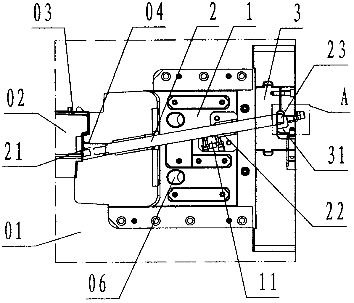
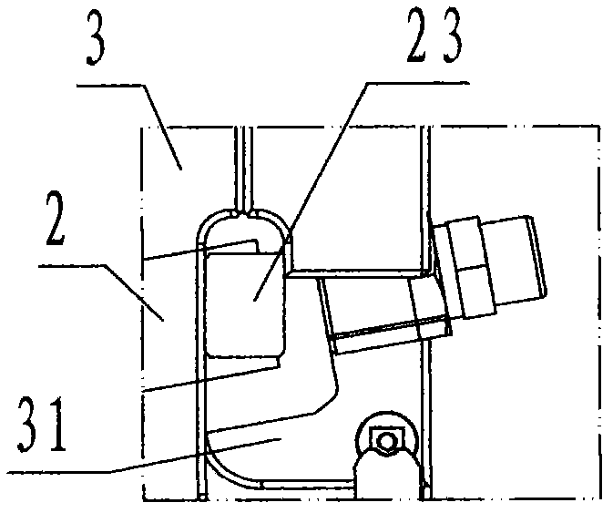
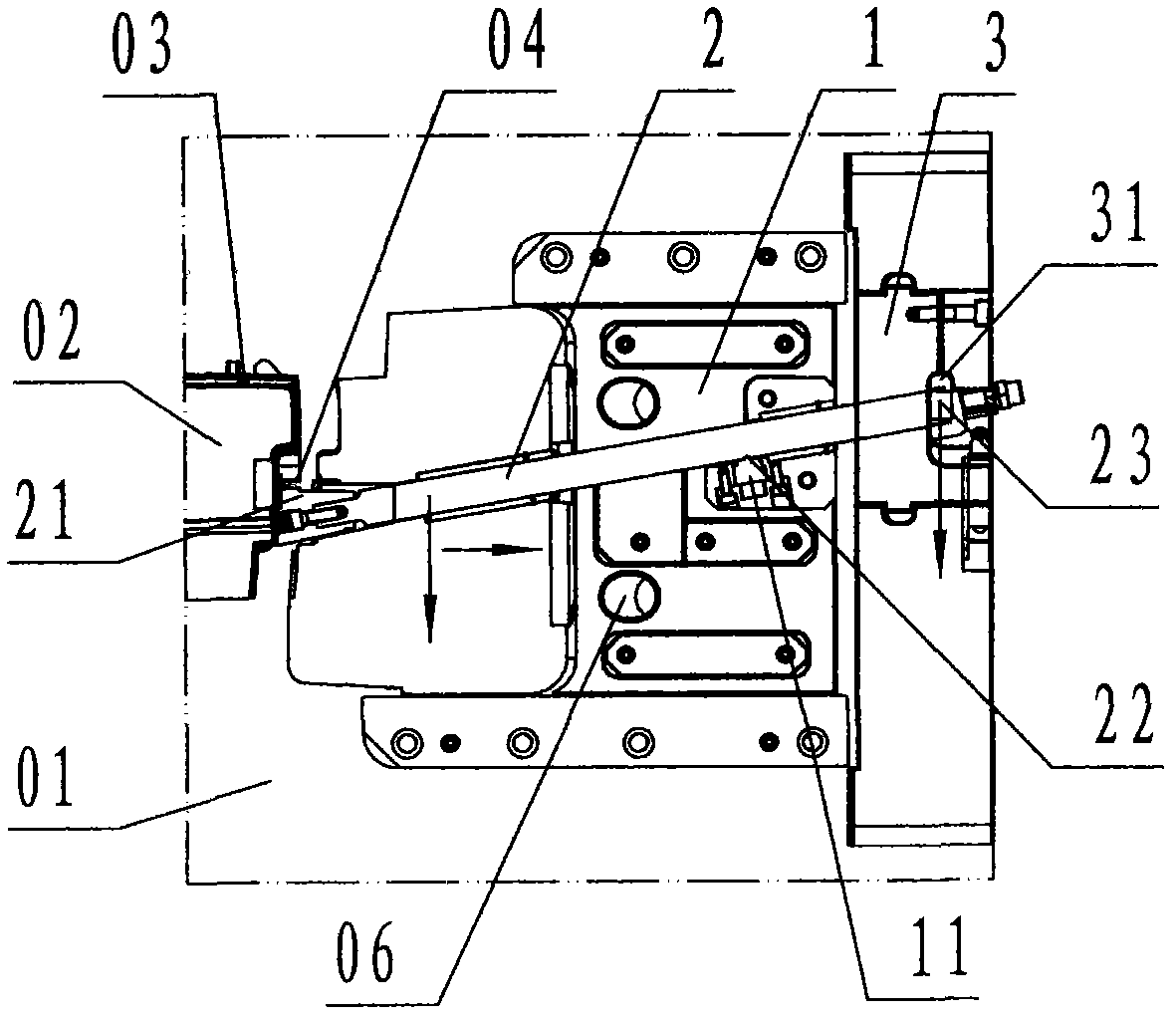
[0023] refer to Figure 1 to Figure 5 , a horizontal inclined top core-pulling device arranged in the horizontal slider of the present invention, comprising a horizontal slider 1, a pin 11, an inclined ejector rod 2, an undercut core block 21, a pin socket 22, a stopper 23, an inclined Top seat 3, containment groove 31, wherein: the horizontal slider 1 is a steel slider that is slidably arranged in front of the movable mold carrier plate 01 and moves outward along the lateral direction of the mold to pull the core; the horizontal slider The left side of 1 is provided with a corresponding profile that coincides with the local profile of the product; the transverse slider 1 is provided with an oblique guide hole 06 that runs through the front and back and is inclined from left to right; The rectangular oblique hole that slopes upward on the right is called the oblique top guide hole;

[0024] In the guide hole of the inclined top, a rectangular long bar-shaped inclined ejector ...


PUM


Abstract

The invention discloses a lateral inclined-knockout core-loosening device arranged in a lateral sliding block. The technical scheme adopted by the invention is as follows: the device comprises a lateral sliding block (1), a ball pin (11), an inclined knockout rod (2), a back-off pellet (21), a pin hole (22), a stop dog (23), an inclined knockout base (3) and a restraining slot (31). The lateral inclined knockout core-loosening device arranged in the lateral sliding block is characterized in that the inclined knockout rod and the back-off pellet are arranged in the lateral sliding block; and during die sinking, the inclined knockout rod and the back-off pellet aslant slide to extend out of the lateral sliding block under the restriction of the stop dog while an inclined guide post drives the lateral sliding block to carry out lateral demoulding, so that the back-off pellet is laterally skew to loosen the core and demould in a back-off mode from a product along the direction orthogonal with the demoulding direction of the lateral sliding block, and therefore the problems and defects of complex structure, high cost, low efficiency and high possibility of generating wastes in the prior art are overcome. The inclined knockout mechanism is arranged in the lateral sliding block, so that the structure of the injection molding mould for laterally skewing to loosen the core and demould in a back-off mode for the product is simplified, the cost is lowered, the demoulding efficiency is improved, and wastes are avoided.

Description

technical field [0001] The invention relates to an inclined-top core-pulling device for an injection mold, in particular to a horizontally-mounted core-pulling device set in the horizontally-sliding block that is used to demould the molded product upside-down with the horizontally-sliding block and pull out the horizontally inclinedly-topped core-pulling device. Inclined top core pulling device. Background technique [0002] The core pulling and demoulding of the injection mold can be divided into longitudinal, transverse and oblique directions. The so-called longitudinal direction is along the opening and closing direction of the injection mold, the so-called transverse direction is the direction orthogonal to the longitudinal direction, and the direction between the longitudinal direction and the transverse direction is oblique. Towards. [0003] In the horizontal slider, the surface where the axis of the oblique drawing direction is parallel to the surface where the axis...

Claims


Application Information

Patent Timeline
Patent Type & Authority Applications(China)
IPC IPC(8): B29C45/33
Inventor 徐威宇方永杰李金岳文黎清
Owner NINGBO FANGZHENG TOOL
Why Eureka
Try Eureka