Rigid rotor system for helicopter

A helicopter and rigid technology, applied in the aviation field, can solve the problems of poor maintainability, complex mechanical structure, short life, etc., and achieve the effect of simple structure, good maintainability and long life

Active Publication Date: 2016-02-03
维拓(南京)智能技术有限公司
View PDF6 Cites 8 Cited by
  • Summary
  • Abstract
  • Description
  • Claims
  • Application Information

AI Technical Summary

Problems solved by technology

[0006] (1) Complex mechanical structure, heavy weight, short life and poor maintainability;
[0007] (2) When flying forward at high speed, the compensation effect of the angle of attack generated by the waving of the backward blade makes it easier to enter the aerodynamic stall state, thereby reducing its aerodynamic efficiency

Method used


Image

  • Rigid rotor system for helicopter
  • Rigid rotor system for helicopter
  • Rigid rotor system for helicopter

Examples


Embodiment Construction

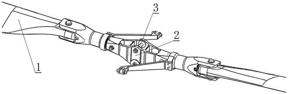
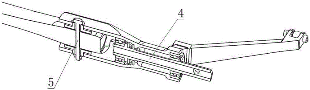
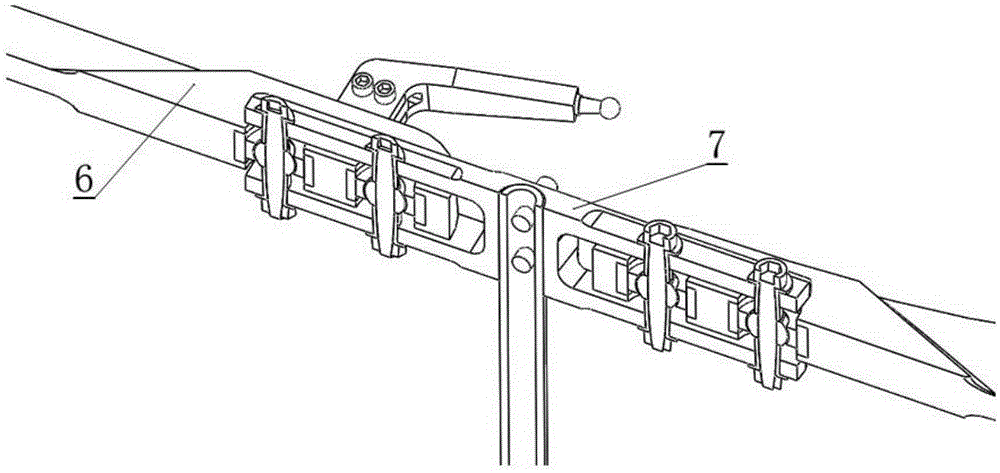
[0021] See figure 1 — Figure 5 , the present invention will be further described below in conjunction with accompanying drawing.

[0022] In order to overcome the deficiencies of the prior art, according to the embodiment of the present invention, see Figure 3-Figure 5 , provides a rigid rotor system for helicopters, which overcomes the problems of complex structure, heavy weight and short life of conventional seesaw propeller hubs of helicopters, and at the same time avoids that the backward propellers are more likely to enter the aerodynamic stall state due to waving when flying forward at high speed Therefore, problems such as aerodynamic efficiency are reduced, and the utility model has the advantages of simple structure, light weight, long life and good maintainability.

[0023] See Figure 3-Figure 5 , the rigid rotor system of a kind of helicopter of present embodiment, it mainly comprises rigid rotor hub 7, rigid rotor pitch change mechanism and rigid rotor blade ...


PUM


Abstract

The invention discloses a rigid rotor system for a helicopter. The rigid rotor system comprises a rigid rotor propeller hub, a rigid rotor pitch control mechanism and rigid rotor paddles, wherein the rigid rotor pitch control mechanism and the rigid rotor paddles are glued integrally and are connected with the rigid rotor propeller hub by virtue of bolts. According to the system disclosed by the invention, deep groove ball bearings and thrust bearings in the conventional teeterboard type propeller hub structure are replaced by joint bearings, so that a series of complex structures such as pitch change shafts, flapping hinges and vertical hinges are removed, and the problems such as complexity of the conventional teeterboard type propeller hub structure, heavy weight and short service life can be solved. Meanwhile, the problems that retreating paddleseasily enter an aerodynamic stalling state so as to reduce the aerodynamic efficiency due to swinging during high-speed forward flight and the like are solved, and the rigid rotor system has the advantages of simple structure, light weight, long service life, high maintainability and the like.

Description

technical field [0001] The invention relates to the field of aviation technology, in particular to a rigid rotor system of a helicopter. Background technique [0002] see figure 1 and figure 2 , the traditional helicopter rotor system generally includes three hinges (that is, three degrees of freedom), which are respectively the traditional rotor pitch variable hinge 4 that controls the change of the pitch angle of the traditional rotor blade 1, allowing the traditional rotor blade 1 to operate in flight. The traditional rotor flapping hinge 3 that swings up and down and the traditional rotor swing hinge 5 that allows the traditional rotor blade 1 to move back and forth during flight. [0003] The main cause of the waving motion of the traditional rotor blade 1 is that when the helicopter flies forward, the rotation motion of the traditional rotor blade 1 and the forward flight motion are superimposed. Taking the counterclockwise rotation of the rotor in the top view as a...

Claims


Application Information

Patent Timeline
Patent Type & Authority Applications(China)
IPC IPC(8): B64C27/43
Inventor 胡奉言
Owner 维拓(南京)智能技术有限公司
Why Eureka
Try Eureka