Spinning machine with thread suction device

A technology of spinning machine and equipment, applied in the field of spinning machine, can solve problems such as disconnection and cost

Active Publication Date: 2015-09-02
MASCHINENFABRIK RIETER AG
View PDF15 Cites 0 Cited by
  • Summary
  • Abstract
  • Description
  • Claims
  • Application Information

AI Technical Summary

Problems solved by technology

[0006] Today, conventional suction systems have the disadvantage that they continuously suck air through all suction tubes during the spinning process, especially independently of the occurrence of thread breaks
Furthermore, a high overall suction capacity also entails correspondingly large suction components, such as drives and fans, with corresponding cost consequences

Method used


Image

  • Spinning machine with thread suction device
  • Spinning machine with thread suction device
  • Spinning machine with thread suction device

Examples


Embodiment Construction

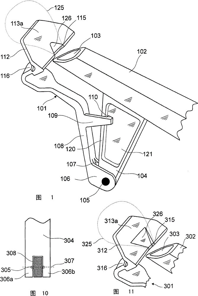
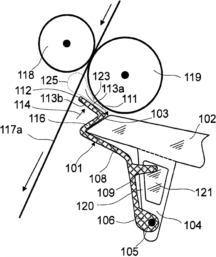
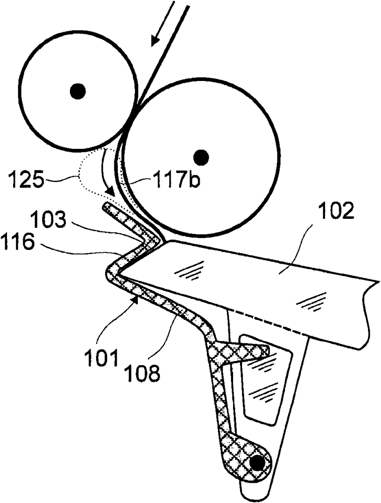
[0070] figure 1 and Fig. 2 shows a first embodiment of a first variant of the invention, Figure 7 A second embodiment is shown. image 3 and Figure 4 shows a first embodiment of the second variant of the invention, Figure 5 with Image 6 A second embodiment is shown. Figure 8 with Figure 9 Another embodiment of the first and third variants of the invention is shown.

[0071] according to figure 1 , 3 The suction pipe 2, 102, 202 of and 8 includes a tongue-shaped part 4, 104, 204 integrally formed with the pipe, and the closing part 1, 101, 201 is connected to the tongue-shaped part integrally formed with the pipe through a swivel joint 5, 105, 205 part. The swivel joint 5 , 105 , 205 consists of two tenons connected to the tongue-shaped part 4 , 104 , 204 integrally formed with the tube and guided through two tabs 6 on the closing part 1 , 101 , 201 , 106, 206; 7, 107, 207 holes or recesses, two tabs 6, 106, 206; Of course, the tenon could also be provided on the...


PUM


Abstract

The machine has a thread suction opening (103) attached to spinning points. A locking mechanism is provided with a locking body (101) i.e. covering flap. The mechanism is attached at the thread suction opening. The locking body is held against the opening. The locking body comprises a guiding unit (112) in form of tongue, where pressure force acts on the guiding unit, during spinning operation at the points. The body is held at the opening by the pressure force that occurs against resetting force acting on the body under minimizing an air passage section at a thread suction tube (102).

Description

technical field [0001] The invention relates to a spinning machine with a plurality of spinning stations, each comprising a drafting device and a twisting device, and a thread suction device with a plurality of thread suction tubes, the plurality of spinning Each of the thread suction tubes has at least one thread suction hole for sucking off the sliver after thread breakage, and the spinning stations are each assigned a thread suction hole with an air passage cross section. Background technique [0002] In spinning machines, such as ring spinning machines, thread breakage occurs repeatedly during spinning. That is to say, the yarn sliver is cut off at the portion between the pair of delivery rollers of the drafting device and the yarn bobbin, thereby interrupting the spinning process. However, the drafting devices, which are usually not independently driven, continue to work and continue to feed the strands of material to the twisting device. The sliver that is continuous...

Claims


Application Information

Patent Timeline
Patent Type & Authority Patents(China)
IPC IPC(8): D01H11/00D01H13/04
CPCD01H5/68
Inventor E·克雷西L·马利纳R·纳格利G·施奈德
Owner MASCHINENFABRIK RIETER AG
Why Eureka
Try Eureka