Energy dissipator for architectural drainage system

A technology for building drainage and energy dissipators, which is applied to buildings, water supply installations, indoor sanitary piping installations, etc., can solve the problems of insufficient strength, large drainage noise, and occupying building space, so as to avoid negative pressure suction and reduce Drainage noise, the effect of increasing the drainage capacity

Active Publication Date: 2010-09-29
浙江中财管道科技股份有限公司
View PDF5 Cites 14 Cited by
  • Summary
  • Abstract
  • Description
  • Claims
  • Application Information

AI Technical Summary

Problems solved by technology

[0002] At present, it is very common to use UPVC plastic pipes in building drainage systems. However, compared with cast iron pipes, plastic pipes have the disadvantages of insufficient strength and relatively high noise. Small, the potential energy of the water flow is large, so that the water flow velocity in the standpipe is large, which has a great influence on the strength, sealing and stability of the drainage system of the pipe. When hard debris falls with the water flow, it is easy to damage the elbow at the bottom of the standpipe
In order to reduce the flow velocity of the water flow in the standpipe and reduce the influence of the potential energy of the water flow on the pipeline, high-rise buildings generally install an energy dissipation device every 6 floors. A simple energy-dissipating device (such as figure 1 shown)
[0003] The main disadvantage of the above-mentioned simple energy dissipation device is that the drainage noise is loud, and the residents are unwilling to install it in the floor, or even take it away without permission. Another disadvantage is that it takes up a lot of building space
Because of the above-mentioned defects of this simple energy dissipation device, at present, there are no specific corresponding measures for the energy dissipation of high-rise buildings in national regulations, and there are only some local standards, such as the Zhejiang Provincial Standard Design Atlas "Installation Drawings for Rigid PVC Drainage Pipes" "It is mentioned that a simple energy dissipation device should be installed on the drainage risers of high-rise buildings from the 6th floor, and one for every 6th floor upwards.

Method used


Image

  • Energy dissipator for architectural drainage system
  • Energy dissipator for architectural drainage system
  • Energy dissipator for architectural drainage system

Examples


Embodiment Construction

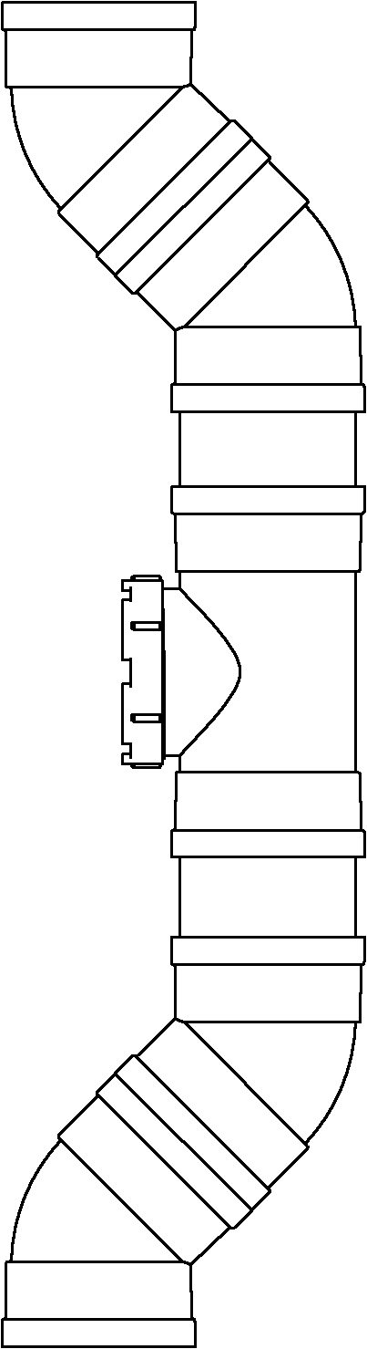
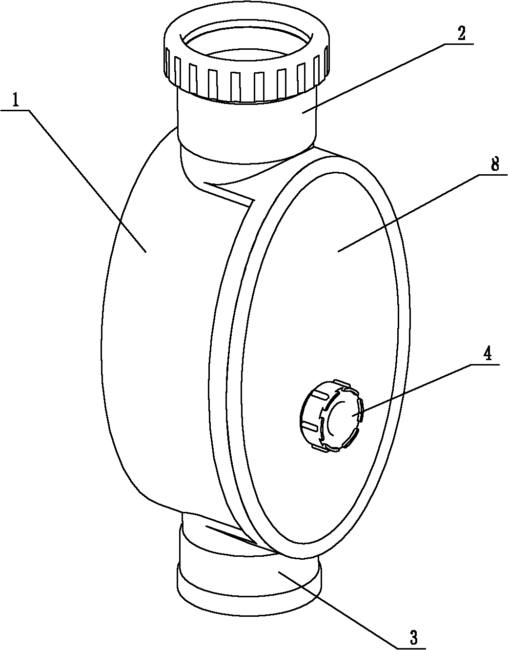
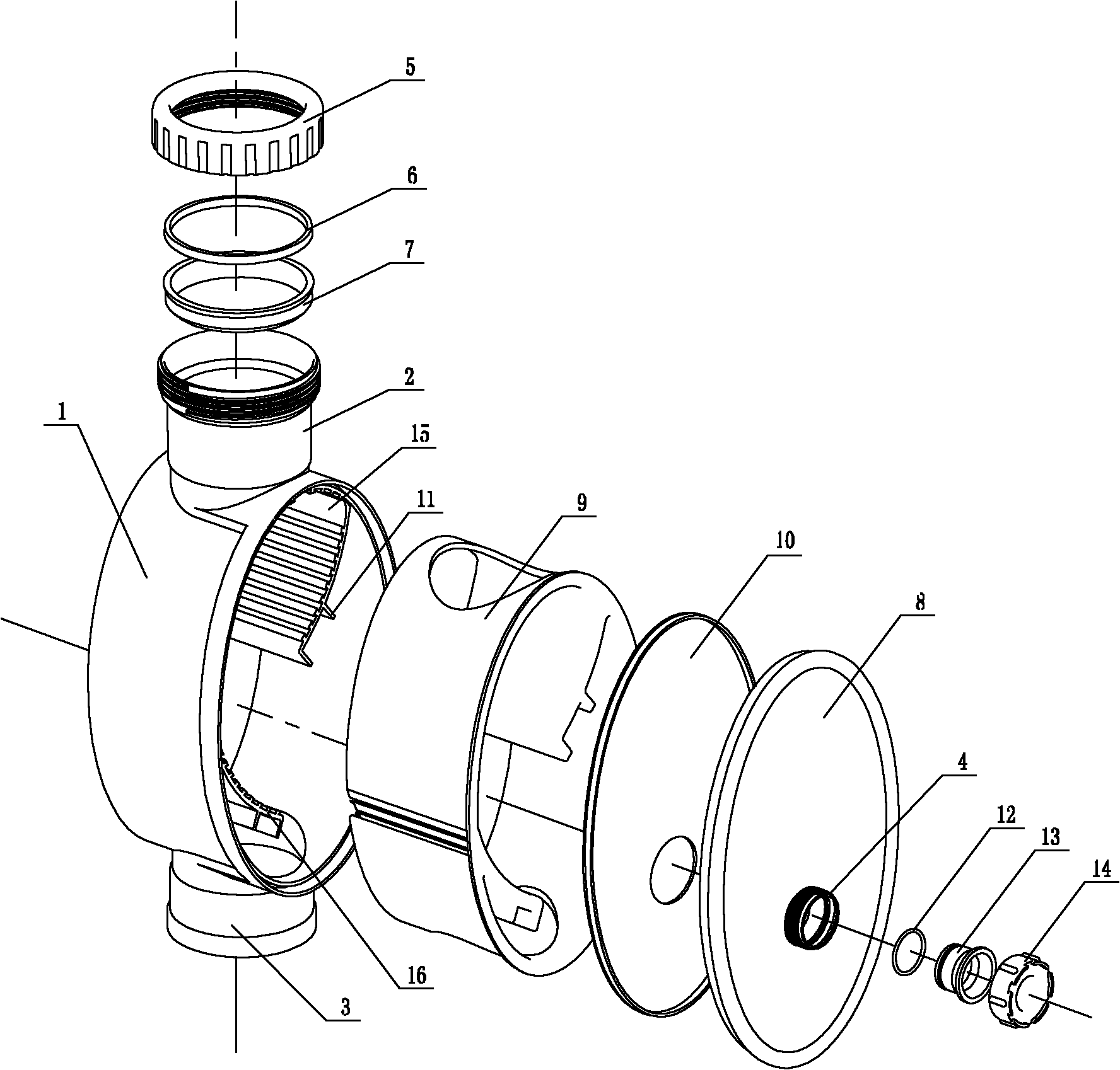
[0021] As shown in the figure, the main body 1 of the energy dissipator has an elliptical shape, and the inner cavity of the main body 1 has two gradually changing arc-shaped water flow baffles 15 and 16 arranged up and down. The main body soft liner 9 applied on the main body inner wall and the water flow baffle has a through hole on its upper and lower parts, and the inner cavity of the main body soft liner communicates with the riser inlet and the outlet respectively. The inner wall of the cover plate 8 is coated with a soft inner lining 10 of the cover plate, and the main body and the cover plate 8 are glued together. An inspection port 4 is provided on the cover plate 8, and the inspection port 4 is connected with a cover 14, and a plug 13 is installed between the inspection port 4 and the cover 14, and the plug 13 is covered with an O-ring 12. The arcs of the water flow baffles 15 and 16 are downward, the width of the water flow baffles is 1 / 3-2 / 3 of the main body width,...


PUM


Abstract

The invention discloses an energy dissipator for an architectural drainage system. A simple and easy energy dissipation device used at present has the defects of large drainage noise, space occupation of a piping shaft and the like. The energy dissipator for the architectural drainage system is characterized in that an inner cavity of a main body is provided with two arc-shaped water flow baffle plates arranged up and down, the arc shapes of the water flow baffle plates are downward, and the width of the water flow baffle plates is 1/3 to 2/3 of the width of the main body; and the upper part of the main body is provided with a stand pipe switching-in port, the stand pipe switching-in port is communicated with the inner cavity of the main body, the lower part of the main body is provided with a stand pipe switching-out port which is communicated with the cavity of the main body. The invention can effectively eliminate the energy of water flow, can also lower the drainage noise and decreases the space of the piping shaft.

Description

technical field [0001] The invention relates to the field of indoor building drainage systems, in particular to an energy dissipator used for rainwater discharge in high-rise buildings. Background technique [0002] At present, it is very common to use UPVC plastic pipes in building drainage systems. However, compared with cast iron pipes, plastic pipes have the disadvantages of insufficient strength and relatively high noise. Small, the potential energy of the water flow is large, so that the water flow velocity in the standpipe is high, which has a great influence on the strength, sealing and stability of the drainage system of the pipe. When hard debris falls with the water flow, it is easy to damage the elbow at the bottom of the standpipe. In order to reduce the flow velocity of the water flow in the standpipe and reduce the influence of the potential energy of the water flow on the pipeline, high-rise buildings generally install an energy dissipation device every 6 flo...

Claims


Application Information

Patent Timeline
Patent Type & Authority Applications(China)
IPC IPC(8): F16L55/02E03C1/122
Inventor 陈增贵刘学敏
Owner 浙江中财管道科技股份有限公司
Why Eureka
Try Eureka