Three-layer sealed wiring structure

A wiring structure and junction box technology, applied in fixed/insulated contact components, clamping/spring connections, electrical components, etc., can solve problems such as easy water ingress, poor sealing effect, short circuit, etc., to prevent leakage short circuit, high quality The effect of the sealing effect

Inactive Publication Date: 2010-09-29
昆山光翼光伏科技有限公司
4 Cites 1 Cited by

AI-Extracted Technical Summary

Problems solved by technology

[0003] In order to solve the problems of poor sealing effect, easy water ingress and...

Method used

As shown in Figures 1 and 2, the three-layer sealed wiring structure includes a step-type sleeve seal 1, an O-shaped seal ring 2, a sealing nut 3 and a wire 9 in a cross section, and the sleeve seal 1 is divided into The upper step 4 and the lower step 5, the height of the upper step 4 is higher than the height of the lower step 5, and the outer surface of the lower step 5 of the sleeve seal 1 is provided with an O-shaped sealing ring 2, and the outer surface of the O-shaped sealing ring 2 A sealing nut 3 is provided. The shell of the junction box is fixedly connected with a hollow square seat 6, and the rear wall 7 of the square seat 6 is provided with a through hole, and the wire 9 passes through the sealing nut 3, the sleeve seal 1, the square Type seat 6, an...

Abstract

The invention discloses a three-layer sealed wiring structure comprising a lead. The three-layer sealed wiring structure is characterized in that the three-layer sealed wiring structure also comprises a sleeve sealing element with a step-shaped cross section, an O-shaped sealing ring and a sealing nut, wherein the sleeve sealing element is divided into an upper step and a lower step; the outer surface of the lower step of the sleeve sealing element is sheathed with an O-shaped seal ring; and the outer side of the O-shaped seal ring is provided with the sealing nut; a hollow square base is fixedly connected on the housing of a junction box; the rear wall of the square base is provided with a through hole; the outer side of the square base is provided with outer screw nuts; the inner side of the sealing nut is provided with inner screw nuts; the square base is sheathed on the outer side of the O-shaped sealing ring to cover the sleeve sealing element and the O-shaped seal ring; and the sealing nut is matched with the thread to tightly press the square base. The invention solves the problem that the contact position of the junction box and the lead has poor sealing effect, is easy to flood and has short circuit in the prior art. The invention provides a three-layer sealed wiring structure with simple structure, convenient use and better sealing effect.

Application Domain

Securing/insulating coupling contact membersClamped/spring connections

Technology Topic

Screw capEngineering +3

Image

  • Three-layer sealed wiring structure
  • Three-layer sealed wiring structure
  • Three-layer sealed wiring structure

Examples

  • Experimental program(1)

Example Embodiment

[0011] The present invention will be further described
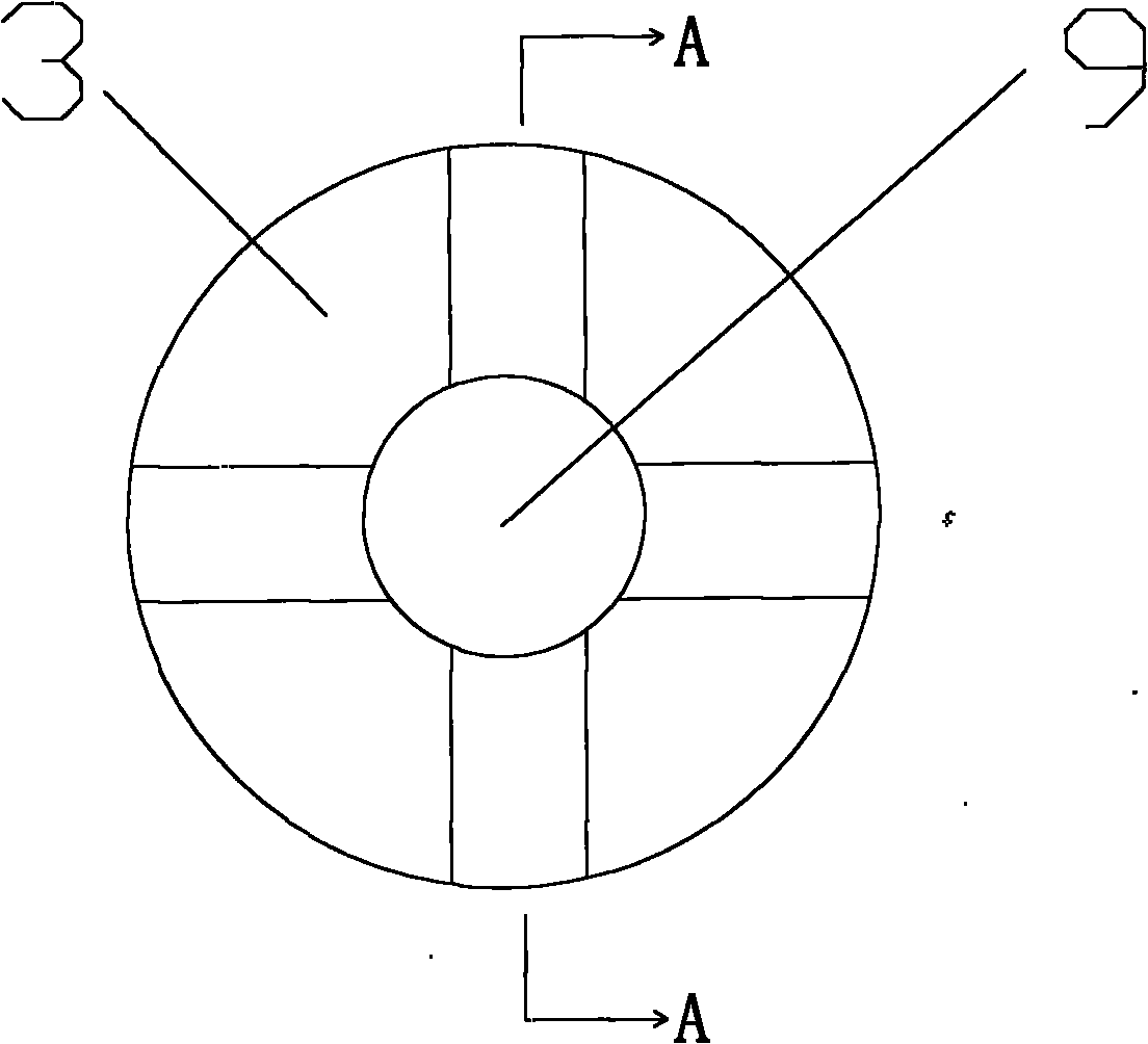
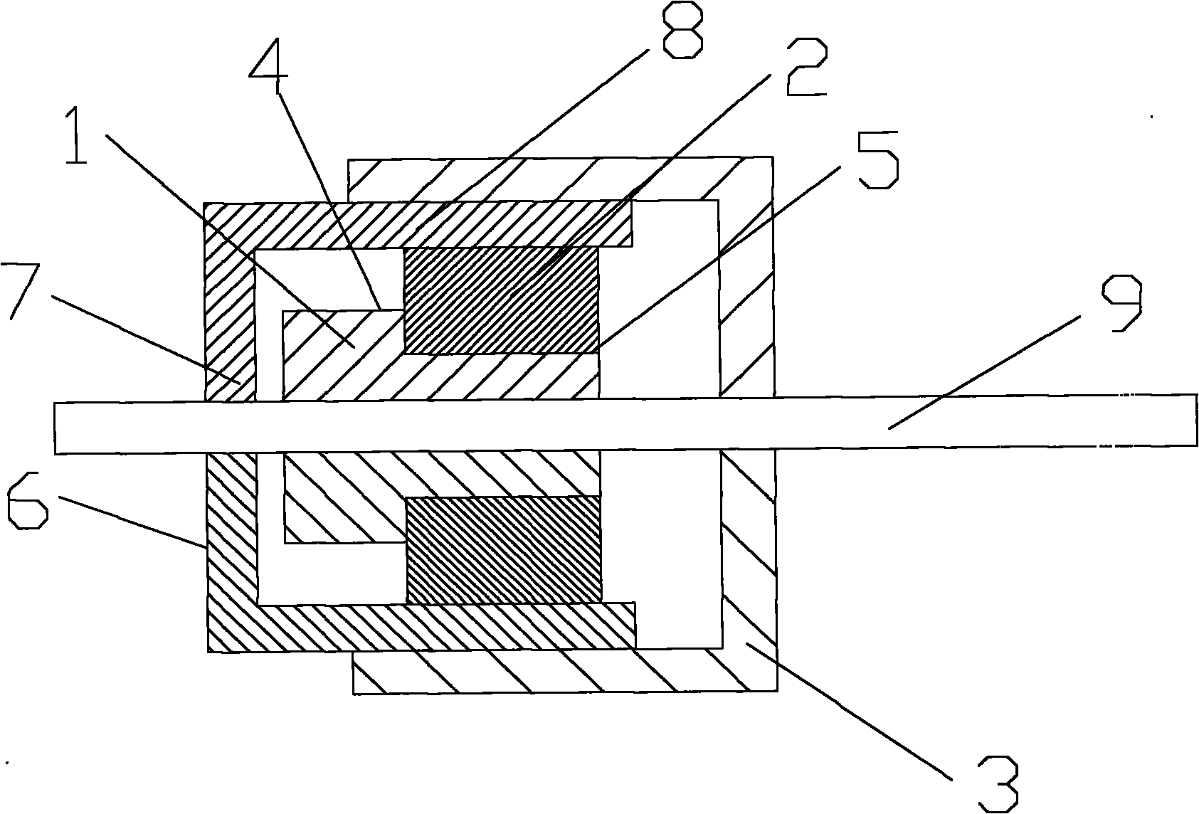
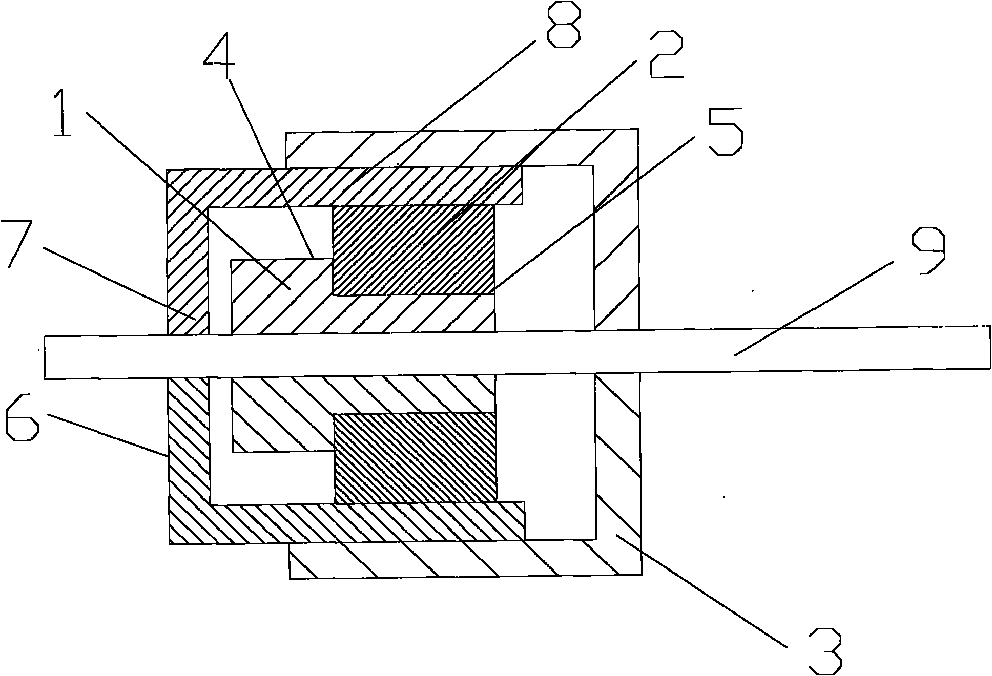
 below in conjunction with the drawings
[0012] Such as figure 1 with 2 As shown, the three-layer sealed wiring structure includes a stepped sleeve seal 1, an O-ring seal 2, a sealing nut 3, and a wire 9. The sleeve seal 1 is divided into an upper step 4 and a lower step 5. The height of the upper step 4 is higher than the height of the lower step 5, an O-shaped sealing ring 2 is sleeved on the outer surface of the lower step 5 of the sleeve seal 1, and a sealing nut 3 is provided on the outer side of the O-shaped sealing ring 2. A hollow square seat 6 is fixedly connected to the housing of the junction box, a through hole is provided on the rear wall 7 of the square seat 6, and the wire 9 passes through the sealing nut 3, the sleeve seal 1, the square in turn. Type seat 6 is connected with the circuit inside the junction box; an external thread is provided on the outside of the square seat 6, an internal thread is provided on the inside of the sealing nut 3, and the side wall 8 of the square seat 6 is sleeved on the O-shaped seal The outer side of the ring 2 wraps the sleeve seal 1 and the O-shaped seal ring 2, and the upper step 4 of the sleeve seal 1 is closer to the rear wall 7 of the square seat 6. The sealing nut 3 is fitted with threads Press the square seat 6 tightly. The sleeve seal 1 is provided with an upper step 4, which can play a role in resisting the O-ring 2 so that the O-ring 2 will not fall off the sleeve seal 1 during the rotation and tightening process of the sealing nut 3 Falling off strengthens the sealing effect and prolongs the service life.
[0013] The basic principles and main features and advantages of the present invention are shown and described. Those skilled in the industry should understand that the present invention is not limited by the foregoing embodiments. The foregoing embodiments and descriptions only illustrate the principles of the present invention. Without departing from the spirit and scope of the present invention, the present invention may have Various changes and improvements, these changes and improvements fall within the scope of the claimed invention. The scope of protection claimed by the present invention is defined by the appended claims and their equivalents.

PUM

no PUM

Description & Claims & Application Information

We can also present the details of the Description, Claims and Application information to help users get a comprehensive understanding of the technical details of the patent, such as background art, summary of invention, brief description of drawings, description of embodiments, and other original content. On the other hand, users can also determine the specific scope of protection of the technology through the list of claims; as well as understand the changes in the life cycle of the technology with the presentation of the patent timeline. Login to view more.
Why Eureka
Try Eureka