Supercharge Your Innovation With Domain-Expert AI Agents!

Load control system

A technology of load control system and control unit, applied in transmission systems, digital transmission systems, telemetry/remote control selection devices, etc., can solve problems such as prolonging time and increasing load

Inactive Publication Date: 2010-09-29
PANASONIC CORP
View PDF4 Cites 5 Cited by
  • Summary
  • Abstract
  • Description
  • Claims
  • Application Information

AI Technical Summary

Problems solved by technology

Therefore, when the operator terminal tries to control multiple loads at the same time, it is possible to control each load at a different time
Also, increasing the number of loads extends the time required to control all loads

Method used


Image

  • Load control system
  • Load control system
  • Load control system

Examples


Embodiment Construction

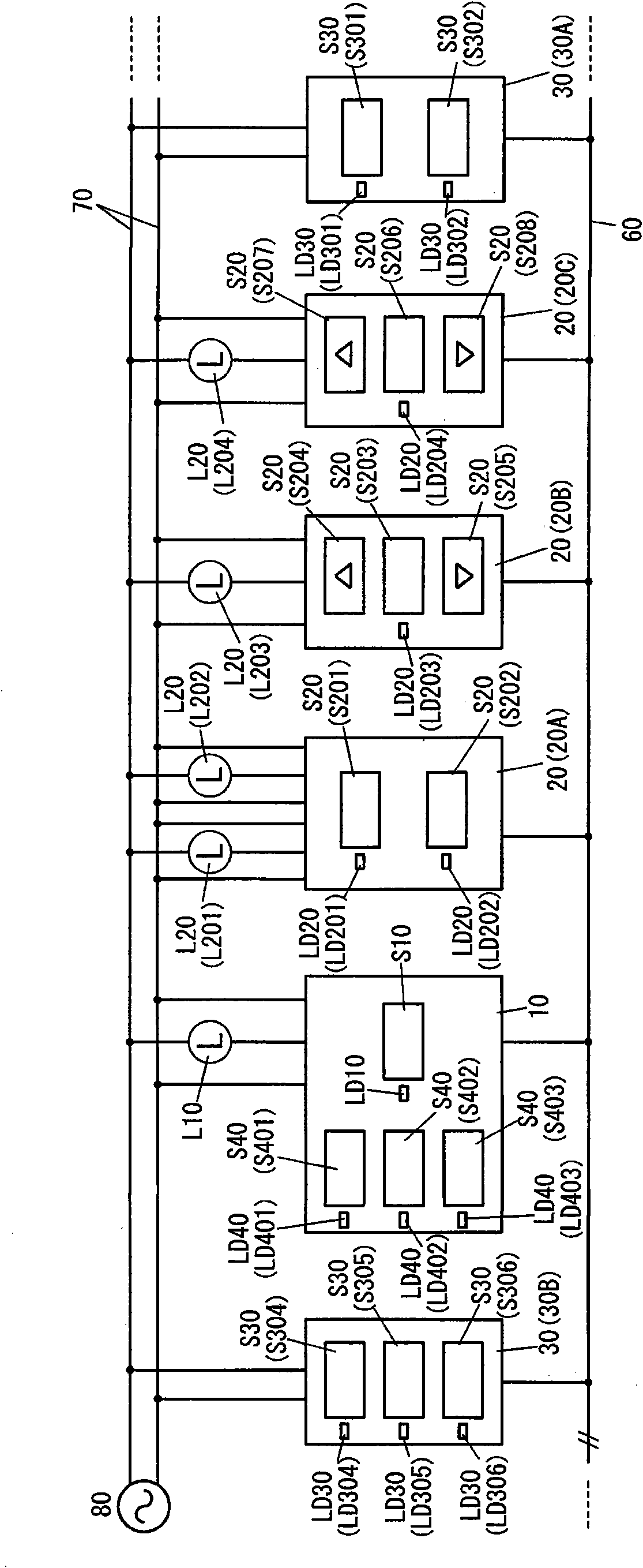
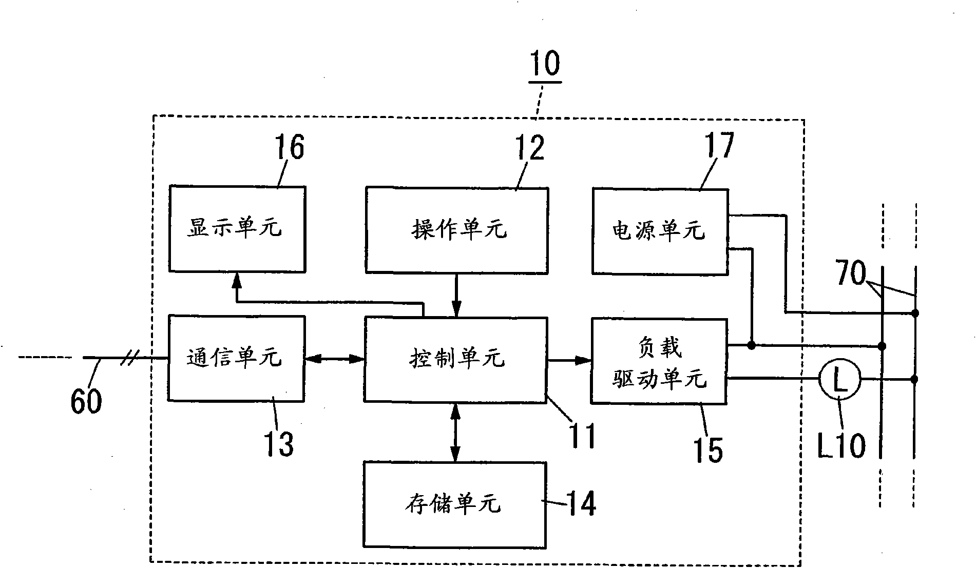
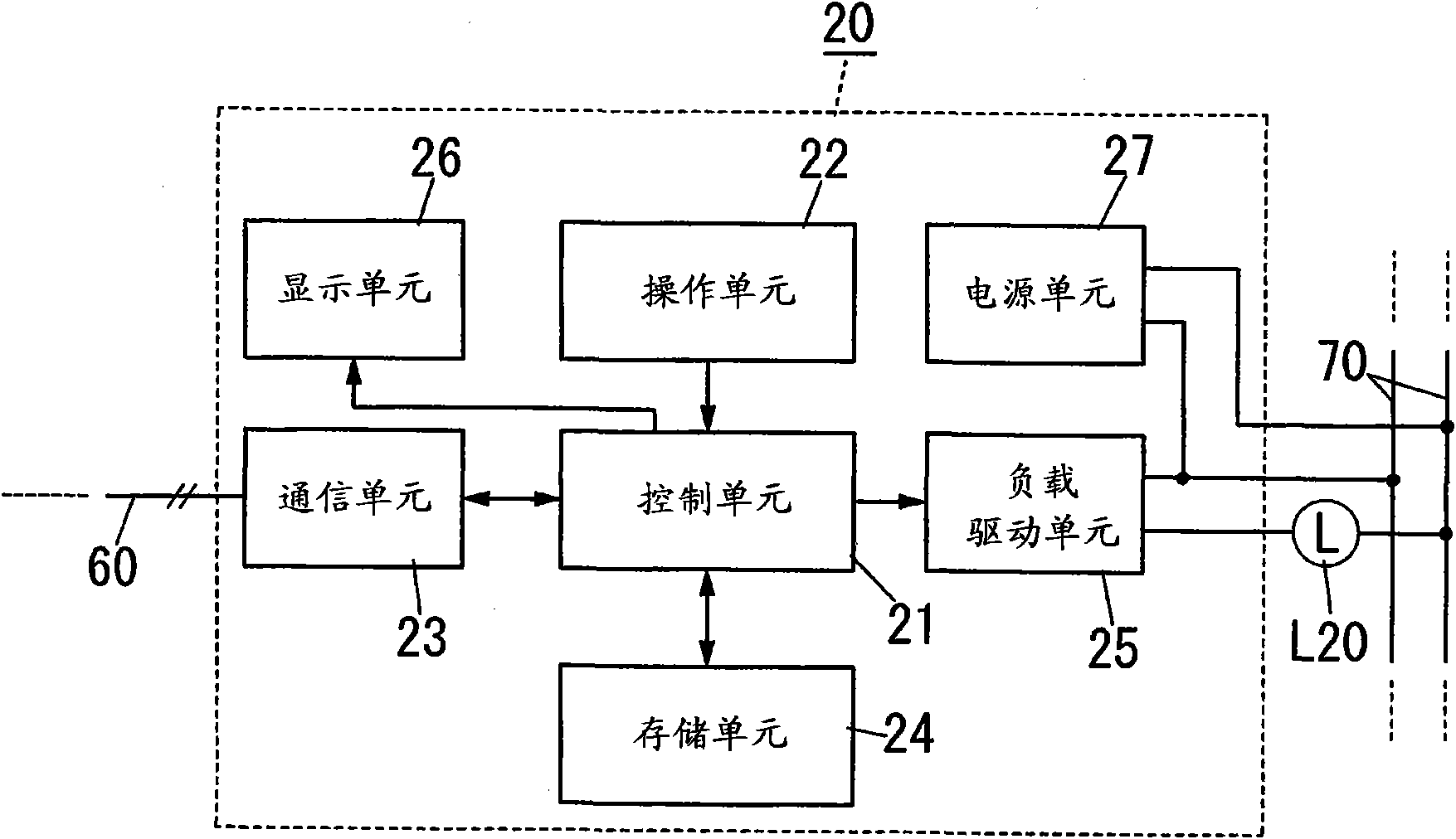
[0026] Now, refer to figure 1 , shows a load control system according to a preferred embodiment of the present invention. The load control system is suitable for controlling a plurality of loads L. This load control system has a first terminal (first operation control terminal) 10, a plurality of second terminals (second operation control terminals) 20 (20A, 20B, and 20C), and a plurality of third terminals (operation terminals) 30 ( 30A and 30B). The terminals 10 , 20 and 30 are connected to each other by a two-wire signal line 60 .

[0027] The load L includes a first load L10 and a plurality of second loads L20 ( L201 , L202 , L203 and L204 ). The first load L10 is connected to the first terminal 10 . Second loads L201 and L202 are connected to the second terminal 20A. The second loads L203 and L204 are connected to the second terminals 20B and 20C, respectively.

[0028] For example, each of loads L10 and L20 is a lighting load. Loads L10 and L20 are connected to an...


PUM


Abstract

The invention relates to a load control system, including a first terminal and a plurality of second terminals connected to the first terminal through signal lines. The second terminal responds to the manual operation control of a second switch and connects to its second load. The first terminal responds to the manual operation control of a first switch and connects to its first load. The first terminal responds to the manual operation of a fourth switch and generates a data packet including data and destination address and outputs the data packet to the signal line. The data includes a second identifier (ID) of the second terminal corresponding to the manually operated fourth switch and a second control command for controlling the second load. The destination address represents a first multicast address. The second terminal receives the data packet of the destination address representing the first multicast address. When a specific second ID is included in data in the received data packet, the second terminal gains a second control command correlated with the specific second ID from data and controls the second load corresponding to gained second control command.

Description

technical field [0001] The present invention relates to load control systems, and more particularly, to load control systems for controlling a load in response to manual operation of a switch. Background technique [0002] Document 1 (Japanese Patent Publication JP 2003-37879A) discloses a load control system employing time division multiplexing. [0003] The load control system disclosed in Document 1 has a transport control device. The transmission control device is connected to a plurality of operation terminals and a plurality of control terminals via a two-wire signal line. Each operation terminal has a switch of a manual operation type, and each control terminal controls a load (for example, a lighting load). [0004] In the load control system described above, the control terminal and the operation terminal communicate with each other through the transmission control means. That is, the load control system described above is a so-called integrated control system. ...

Claims


Application Information

Patent Timeline
IPC IPC(8): H04L12/56H04Q9/00
CPCH04L47/125H04L47/15
Inventor 平田聪松浦修次藤田裕司兵主春彦
Owner PANASONIC CORP
Features
  • R&D
  • Intellectual Property
  • Life Sciences
  • Materials
  • Tech Scout
  • Unparalleled Data Quality
  • Higher Quality Content
  • 60% Fewer Hallucinations
Learn More