
Self-contained infusion support

An infusion stand and its own technology, applied in the field of infusion stands, can solve problems such as weak positioning connections and damage to patients' infusion connections

Inactive Publication Date: 2010-10-06
游素贞
View PDF6 Cites 8 Cited by
  • Summary
  • Abstract
  • Description
  • Claims
  • Application Information

AI Technical Summary

Problems solved by technology

However, the positioning connection between the "ten" frame and the patient is not firm, the "ten" frame will shake left and right, the upper and lower positions of the infusion bottle will change, and the infusion pressure will vary. Moreover, the shaking may also damage the patient's infusion connection.

Method used


Image

  • Self-contained infusion support
  • Self-contained infusion support
  • Self-contained infusion support

Examples


Embodiment 1

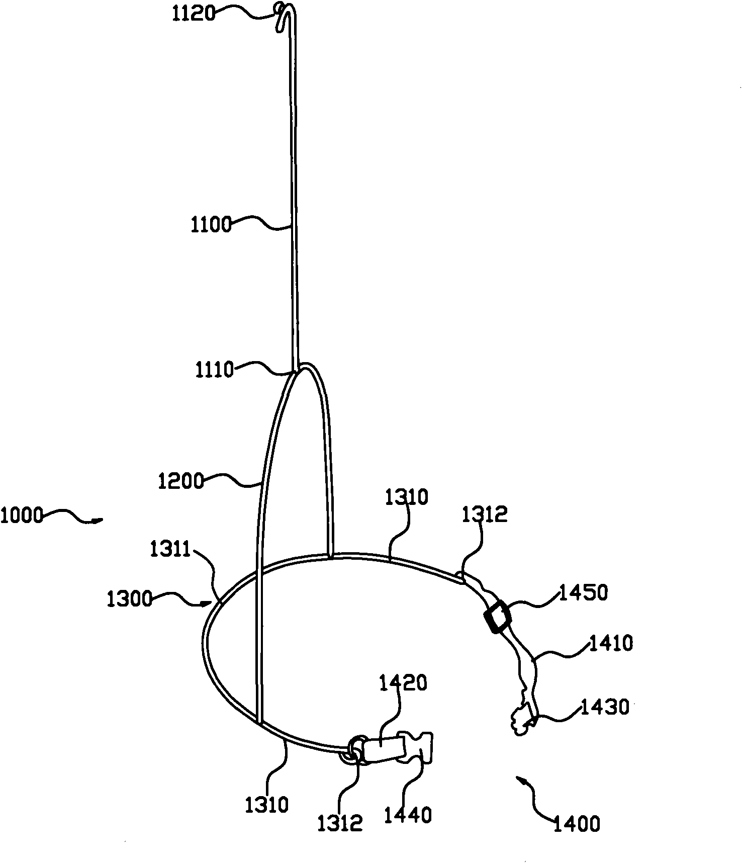
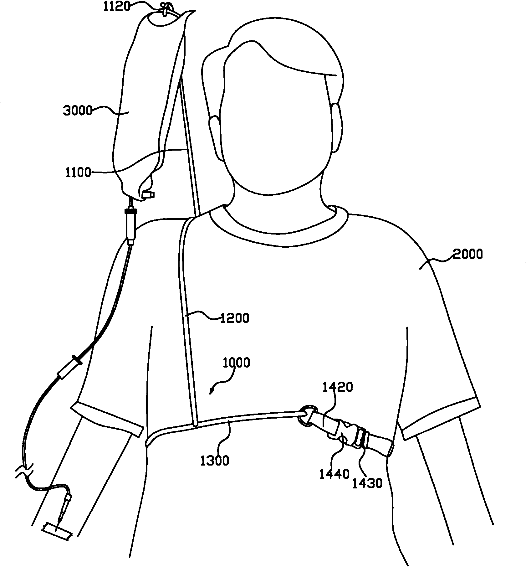
[0033] Please check figure 1 , self-contained infusion stand 1000, which includes a support frame and a suspension frame 1100.

[0034] The support frame includes a U-shaped shoulder frame 1200 and a connecting mechanism. The U-shaped shoulder frame 1200 opens downward and has two lower open ends. The connecting mechanism includes a U-shaped support frame 1300 and a fastening mechanism 1400. The U-shaped support frame 1300 has two symmetrical connecting rods 1310 front and rear. (The two connecting rods 1310 are integrally formed into a U-shaped support frame 1300), the front ends of the two connecting rods 1310 are right open ends 1312, and a ring is provided at the right open ends 1312 for ease of connection. There is also a connection point on the connecting rod 1310, and the left and right distance between the connection point and the common connection end 1311 is 2-15cm. The maximum value is 5-12, the smaller value is 4-10 for domestic sales), and different values ​​ar...

Embodiment 2

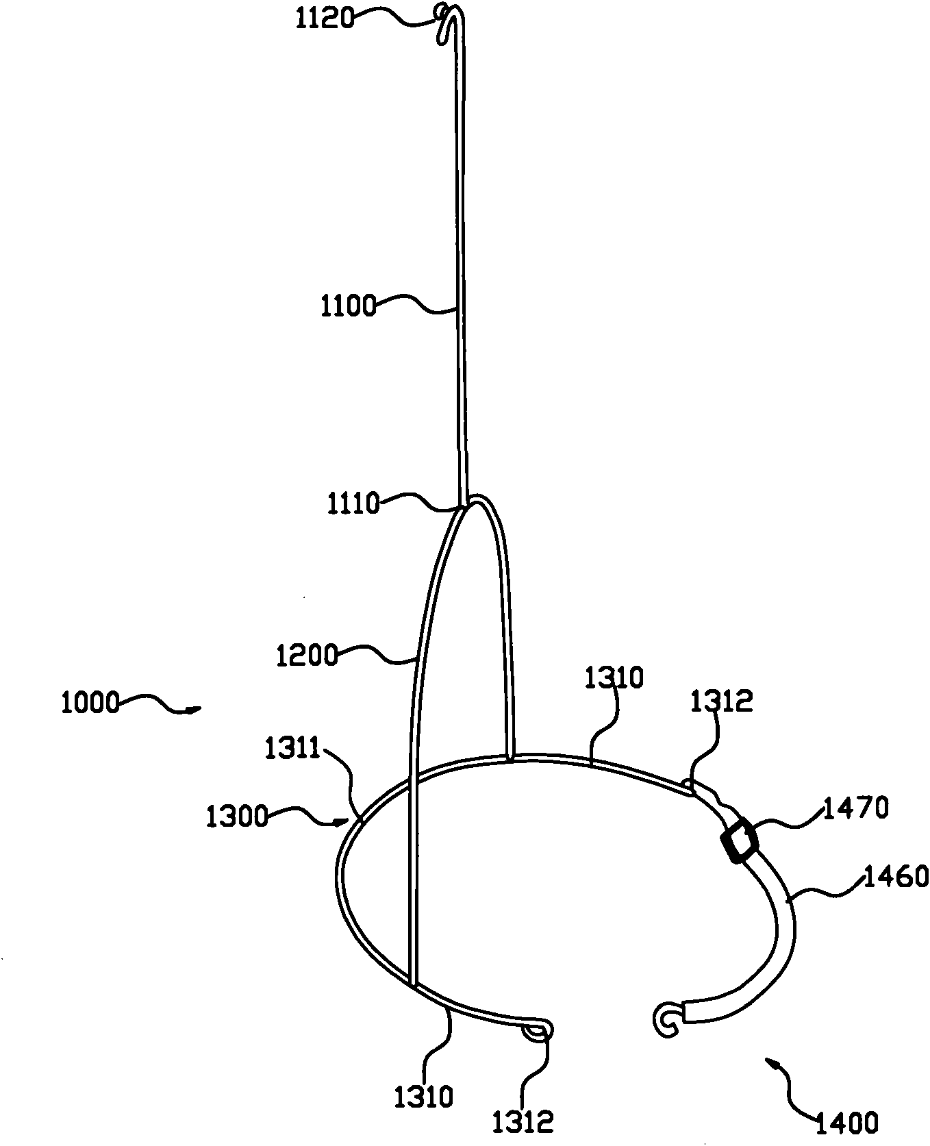
[0039] The difference between this embodiment and the first embodiment is: Please refer to image 3 , the fastening mechanism 1400 includes a flexible belt 1460, one end of the flexible belt 1460 is connected to a ring at a right open end 1312 of a connecting rod 1310, and the other end is provided with a hook, which can be hooked to another On the ring part of a right open end 1312 of the connecting rod 1310; the flexible belt 1460 is provided with a length adjusting buckle 1470 capable of adjusting the length of the first flexible belt.

Embodiment 3

[0041] The difference between this embodiment and the first embodiment is: Please refer to Figure 4 , omitting the fastening mechanism 1400; the two connecting rods 1310 are both elastic rods, the elasticity makes the connecting rod 1310 have an elastic force towards the other connecting rod 1310, through which the U-shaped supporting frame 1300 can be supported against the patient Waist, the connection mechanism can be positioned and connected to the waist of the patient 2000, and the support frame can be supported and connected to the patient 2000.


PUM


Abstract

The invention discloses a self-contained infusion support. The self-contained infusion support comprises a supporting frame and a hanging frame, wherein the supporting frame can be supported against and connected with the body of a user; the hanging frame can hang an infusion bottle; the supporting frame comprises a U-shaped shoulder-carried frame and a connecting mechanism; the shoulder-carried frame can be carried on the shoulder of the user; the connecting mechanism can be positioned at and connected with the waist of the user; the U-shaped shoulder-carried frame is fixedly connected with the connecting mechanism; and the hanging frame is fixedly connected with the shoulder-carried frame. In the invention, the human structurology is skillfully applied to the infusion support; the infusion support is carried on the shoulder of the user through the U-shaped shoulder-carried frame; and the connecting mechanism is positioned at and connected with the waist of the user; therefore the infusion support is firmly supported against and connected with the body of the patient to prevent shaking, constantly keep the infusion bottle and the infusion place vertically, keep constant infusion liquid pressure and protect the infusion joint of the patient.

Description

technical field [0001] The invention relates to an infusion stand, in particular to a self-contained infusion stand. Background technique [0002] Traditional infusion bottles are suspended on immovable fixtures. Adopting this traditional infusion method makes the patient have to sit on a fixed position for a long time, which will make the patient tired and irritable. [0003] For the traditional shortcomings, someone proposed two solutions. [0004] The first one adopts a mobile infusion stand. The mobile infusion stand includes an infusion stand and a roller arranged under the infusion stand. Since the patient can move the infusion stand, the shortcomings of the traditional infusion method are overcome. However, during the moving process, the patient needs to manually move the infusion stand, which is inconvenient to move, and the patient's infusion connection may be damaged during the manual process. [0005] The second type adopts a self-contained infusion stand. T...

Claims


Application Information

Patent Timeline
IPC IPC(8): A61M5/14
Inventor 游素贞
Owner 游素贞
Learn More