Three-way pipe used in control pipelines for evaporation emission of fuel oil

An evaporative emission and pipeline control technology, which is applied in the field of three-way pipes to avoid air blockage, work reliably and reduce costs.

Inactive Publication Date: 2012-06-13
CHONGQING LONCIN MOTOR
View PDF0 Cites 0 Cited by
  • Summary
  • Abstract
  • Description
  • Claims
  • Application Information

AI Technical Summary

Problems solved by technology

[0005] The object of the present invention is to provide a tee pipe used in the fuel evaporative emission control pipeline which is not easy to cause air blockage in the pipeline

Method used


Image

  • Three-way pipe used in control pipelines for evaporation emission of fuel oil
  • Three-way pipe used in control pipelines for evaporation emission of fuel oil
  • Three-way pipe used in control pipelines for evaporation emission of fuel oil

Examples


Embodiment Construction

[0019] The present invention will be further described below in conjunction with drawings and embodiments.

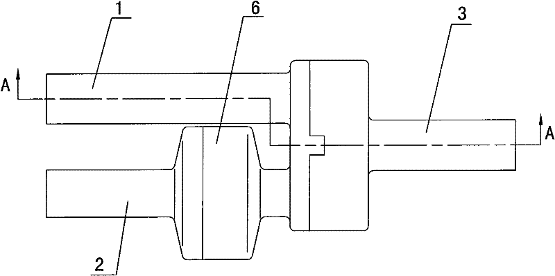
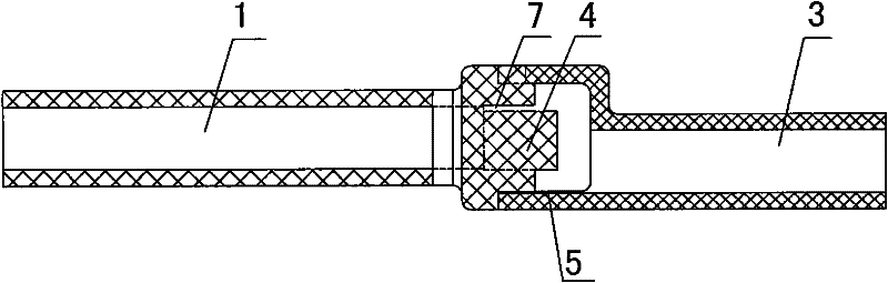
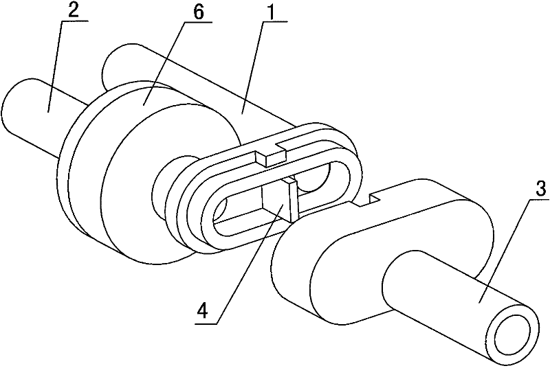
[0020] Such as Figure 1 to Figure 4 As shown, the tee pipe used in the fuel evaporative emission control pipeline has three branch pipes connected as a whole, which are respectively the first branch pipe 1, the second branch pipe 2 and the third branch pipe 3, wherein the first branch pipe 1, the second branch pipe The second branch pipe 2 is formed as the double end of the three-way pipe, and the third branch pipe 3 is the single end of the three-way pipe. There is a baffle 4, and the baffle 4 is located between the interfaces of the inner cavities of the two branch tubes at the double-head end. The baffle plate 4 can stop the liquid gasoline from entering into another branch pipe connected with the one-way valve from one of the pipes at the double end, so as to avoid the air blockage caused by the accumulation of gasoline in the branch pipe. The bottom of the inner...


PUM


Abstract

The invention provides a three-way pipe used in control pipelines for evaporation emission of fuel oil, wherein two branch pipes form a double-head end of the three-way pipe; the orientating direction of the two branch pipes of the double-head end is opposite to that of a branch pipe of a single-head end; a baffle plate is arranged in an inner cavity at the intersection of the three branch pipes and is positioned between interfaces of inner cavities of the two branch pipes of the double-head end; and the bottom of an inner cavity of the branch pipe of the single-head end is lower than the bottoms of the inner cavities of the two branch pipes of the double-head end. By adopting the technical scheme of the invention, the control pipelines for the evaporation emission of the fuel oil can be arranged on a car frame more normatively and compact, the used pipe lamps are fewer, and the cost is reduced; and simultaneously, air blockages caused by fuel oil aggregation in the three-way pipe canbe avoided effectively.

Description

technical field [0001] The invention relates to a three-way pipe, especially a three-way pipe used in a fuel evaporation emission control pipeline. Background technique [0002] The existing gasoline vehicle fuel evaporation pollutant emission control system mainly includes a carbon tank, an intake pipe, an exhaust pipe and a negative pressure pipe. The intake pipe is connected between the carbon tank and the fuel tank, and the exhaust pipe and the negative pressure pipe are connected in the Between the canister and the carburetor, the intake pipe is usually equipped with a dump valve to prevent the gasoline in the fuel tank from entering the canister when the vehicle is dumped. On motorcycles, the carbon canister is fixedly installed on the frame, and the intake pipe, exhaust pipe and negative pressure pipe are generally flexible pipes. Since there are many components installed on the frame and the structure is compact, it is difficult to ensure that the above-mentioned fle...

Claims


Application Information

Patent Timeline
Patent Type & Authority Patents(China)
IPC IPC(8): F02M25/08F16L41/00
Inventor 张俊戴军昌
Owner CHONGQING LONCIN MOTOR
Why Eureka
Try Eureka