Video signal switching system and method

A technology of video signal and switching system, which is applied in the direction of closed-circuit television system, video conferencing system, parts of TV system, etc.

Inactive Publication Date: 2010-10-06
NETAK TECH KO LTD
View PDF0 Cites 18 Cited by
  • Summary
  • Abstract
  • Description
  • Claims
  • Application Information

AI Technical Summary

Problems solved by technology

[0006] This application aims to solve the video jitter problem of the video signal switching system, so as to realize the smooth switching of the video signal

Method used


Image

  • Video signal switching system and method
  • Video signal switching system and method
  • Video signal switching system and method

Examples


Embodiment Construction

[0016] In the following, the video switching system and method of the present application will be described with reference to the accompanying drawings and in combination with exemplary implementations.

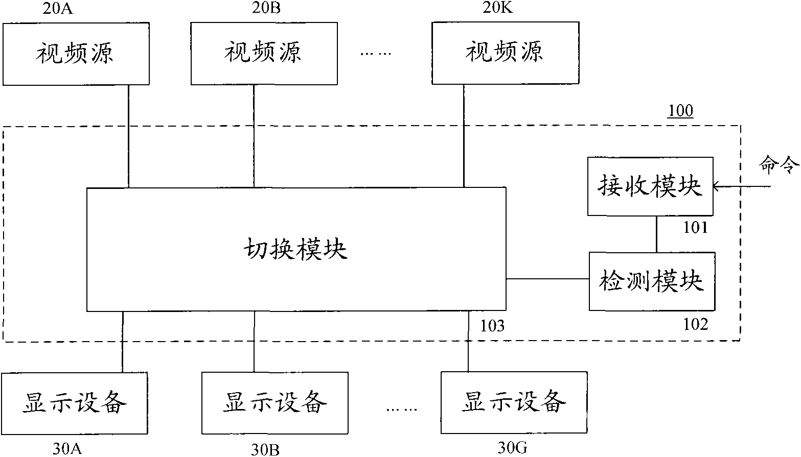
[0017] figure 1 Shown is a video signal switching system 100 according to an exemplary embodiment of the present invention, which can switch and display multiple video signals 20A, 20B, ..., 20K from multiple video sources on one or more display devices 30A , 30B, ..., 30G.

[0018] Such as figure 1 As shown, the video signal switching system 100 includes a receiving module 101 , a detecting module 102 and a switching module 103 . The receiving module 101 receives the switch command and sends a message to the detection module 102 according to the switch command. The detection module 102 detects whether the video signal currently displayed by the display device reaches the field blanking period according to the message. If it is detected that the video signal currently dis...


PUM


Abstract

The invention provides a video signal switching system and a video signal switching method. The system comprises a receiving module, a detecting module and a switching module, wherein the receiving module is used for receiving a command of switching a currently displayed first video signal to a second video signal, and sending a message according to the command; the detecting module is used for detecting whether the first video signal reaches a vertical blanking period according to the message, and if the detected first video signal reaches the vertical blanking period, the detecting module sends a switching command; and the switching module is used for switching the first video signal to the second video signal according to the switching command.

Description

technical field [0001] This application relates to video signal switching. Background technique [0002] Video switching systems are widely used in large conference systems, control systems and monitoring systems. Due to the large number of video sources to be collected, the display device often needs to perform high-density switching among various video sources. [0003] Line and field scanning is usually used in video systems, for example, progressive scanning, interlaced scanning, etc. Each row includes a plurality of image points, and each field includes a plurality of rows. When the scanning beam scans one line from left to right and then scans the next line, the electron gun needs to be turned off. This action is called line blanking. After scanning one field signal and switching to another field signal, the scanning beam returns from the lower right corner to the upper left corner. At this time, the action of closing the electron gun is called field blanking. Duri...

Claims


Application Information

Patent Timeline
Patent Type & Authority Applications(China)
IPC IPC(8): H04N5/268H04N7/18H04N7/15
Inventor 万红波
Owner NETAK TECH KO LTD
Why Eureka
Try Eureka