Image-capturing optical device

A technology of optical device and optical axis, which is applied in the direction of optics, projection device, printing device, etc., can solve problems such as camera shake, and achieve the effect of thinning

Active Publication Date: 2012-03-21
SANKYO SEIKI MFG CO LTD
View PDF4 Cites 13 Cited by
  • Summary
  • Abstract
  • Description
  • Claims
  • Application Information

AI Technical Summary

Problems solved by technology

And mobile devices are prone to camera shake when taking pictures

Method used


Image

  • Image-capturing optical device
  • Image-capturing optical device
  • Image-capturing optical device

Examples


Embodiment Construction

[0055] Hereinafter, embodiments of the present invention will be described based on the drawings.

[0056] (Structure of optical device for photography)

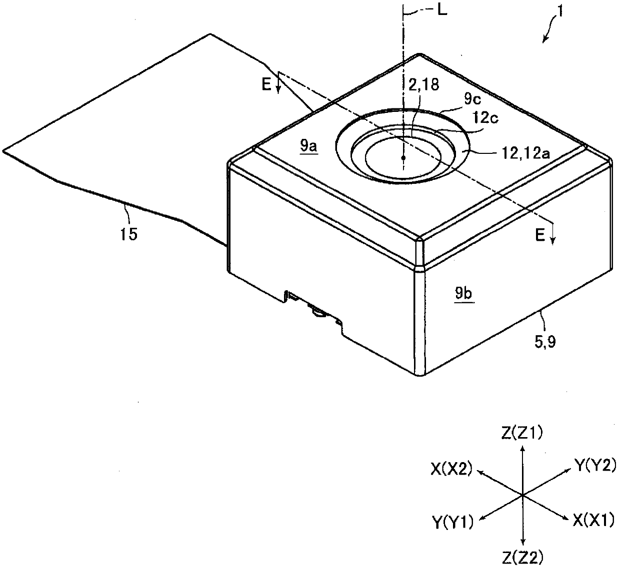
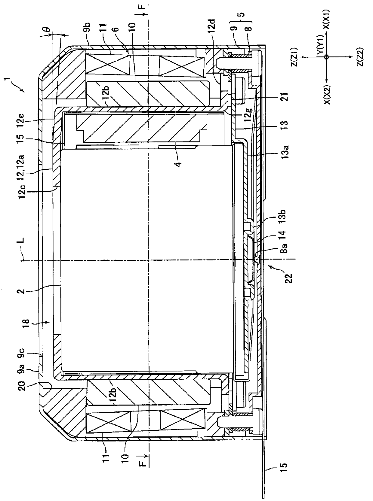
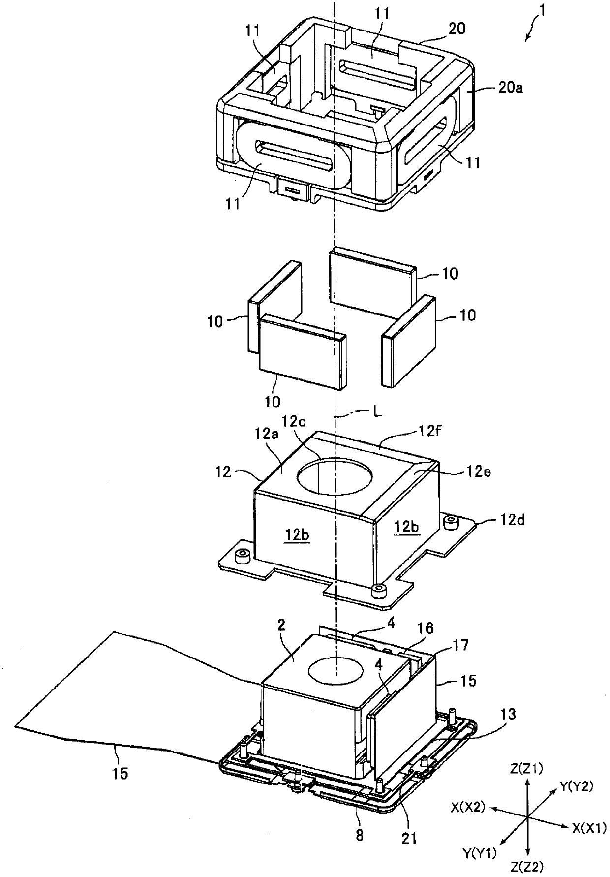
[0057] figure 1 It is a perspective view of the imaging optical device 1 according to the embodiment of the present invention. figure 2 yes figure 1 Sectional view of the E-E section. image 3 yes figure 1 An exploded perspective view of the photographic optical device 1 shown. Figure 4 yes figure 2 Cutaway view of the F-F section. image 3 In , illustration of the casing 9 is omitted.

[0058] In the description below, if figure 1 As shown, the three mutually orthogonal directions are respectively defined as the X direction, the Y direction and the Z direction. Will figure 1 The side in the X1 direction is set to the "right" side, the side in the X2 direction is set to the "left" side, the side in the Y1 direction is set to the "front" side, the side in the Y2 direction is set to the "back" side, and the side i...


PUM


Abstract

An image-capturing optical device which can stably correct hand-shake blur and is thin. An image-capturing optical device (1) comprises: a movable module (18) having a camera module (2) on which a lens and an image-capturing element are mounted; a support body (5) for supporting the movable module (18); and a hand-shake blur-correcting mechanism for correcting hand-shake blur by rocking the movable module (18) in such a manner that the optical axis (L) of the camera module (2) tilts relative to the support body (5). The movable module (18) is provided with a sensor (4) for detecting the tilt of the camera module (2) and also with a cover member (12) for forming the outer peripheral surface of the movable module (18). The sensor (4) is disposed on the inner side of a side surface section (12b) of the cover member (12).

Description

technical field [0001] The present invention relates to an optical device for photographing with a camera shake correction function, which corrects camera shake by swinging a camera unit mounted with a lens and an imaging element. Background technique [0002] In recent years, photographic optical devices have been installed in mobile devices such as mobile phones. And mobile devices are prone to camera shake when taking pictures. Therefore, an optical device capable of correcting camera shake during shooting has been proposed (for example, refer to Patent Document 1). [0003] The optical device described in this patent document 1 includes: a movable part loaded with a lens and an imaging element; a pivot fixed on the base of the optical device and abutting against the bottom surface of the movable part; a leaf spring for supporting the movable part so as to be able to swing; and a swing mechanism for swinging the movable part. In this optical device, the swing mechanism...

Claims


Application Information

Patent Timeline
Patent Type & Authority Applications(China)
IPC IPC(8): G02B7/02G02B7/04G02B7/28G03B5/00G03B13/36H04N5/225
CPCG02B27/646G03B5/00H04N5/2257G03B13/36H04N5/23248H04N5/2251H04N23/57H04N23/55H04N23/68
Inventor 柳泽克重长田章弘武田正南泽伸司武居勇一石原久宽唐泽敏行宫崎清史
Owner SANKYO SEIKI MFG CO LTD
Why Eureka
Try Eureka