Resource block grouping and beam forming method and device

A resource block group and beamforming technology, applied in frequency diversity, space transmit diversity, diversity/multi-antenna systems, etc., can solve problems such as co-channel interference, and achieve the effect of reducing co-channel interference

Inactive Publication Date: 2010-10-06
ZTE CORP
View PDF2 Cites 21 Cited by
  • Summary
  • Abstract
  • Description
  • Claims
  • Application Information

AI Technical Summary

Problems solved by technology

[0005] The technical problem to be solved by the present invention is to propose a resource block grouping beamforming method and device to solve the problem of randomly allocating resource blocks for different users when LTE or LTE-Advanced system Users are allocated to the same resource block, which brings the problem of co-channel interference

Method used


Image

  • Resource block grouping and beam forming method and device
  • Resource block grouping and beam forming method and device
  • Resource block grouping and beam forming method and device

Examples


Embodiment Construction

[0035] The present invention combines resource block grouping and beam selection to design beamforming methods for LTE and LTE-Advanced systems with multiple antennas, that is, to group resource blocks according to certain rules and form corresponding mapping relationships with pre-optimized and designed beams. Different resources The blocks correspond to different beam numbers, and then beamforming is performed. Compared with the traditional random resource block beamforming method, this beamforming method can ensure that different users of two adjacent cells at the edge of the cell are preferentially allocated to different resources. block, thereby effectively reducing inter-cell co-channel interference.

[0036] The present invention will be described in detail below in conjunction with the accompanying drawings and specific embodiments.

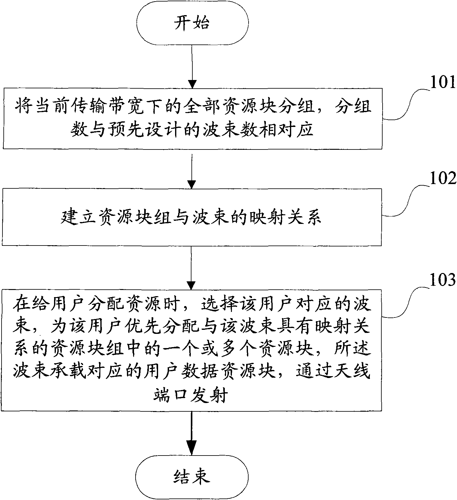
[0037] Such as figure 1 As shown, the method of the embodiment of the present invention includes the following steps:

[0038] Step 10...


PUM


Abstract

The invention discloses a resource block grouping and beam forming method and a resource block grouping and beam forming device. Resource blocks are grouped and grouped resource blocks correspond to wave beams; two adjacent wave beams in different cells map different resource blocks; and two adjacent wave beams in the same cell map different resource blocks. Therefore, co-channel interference among cells is effectively reduced.

Description

technical field [0001] The present invention relates to the field of wireless communication, in particular to a resource block grouping beamforming method and device. Background technique [0002] In the 3Gpp Long-Term Evolution (LTE) system, during data transmission, uplink / downlink time-frequency domain physical resources are formed into resource blocks (Resource Blocks, RBs), which are scheduled and allocated as physical resource units. In the case of a normal cyclic prefix (Normal CP), a physical resource block (Physical Resource Block, PRB) contains 12 consecutive subcarriers in the frequency domain, and contains 7 consecutive OFDM ( Orthogonal Frequency Division Multiplexing (OFDM) symbol, that is, the frequency domain width is 180 kHz, and the time length is 0.5 ms. [0003] The cellular wireless communication system achieves frequency reuse by dividing a large service area into many smaller coverage areas to increase system capacity. Each small coverage area is cal...

Claims


Application Information

Patent Timeline
Patent Type & Authority Applications(China)
IPC IPC(8): H04W16/10H04W16/28H04W16/30H04B7/08H04B7/12
CPCH04W72/04H04B7/0617
Inventor 王衍文李岩张庆宏
Owner ZTE CORP
Why Eureka
Try Eureka