Dynamic distribution method of uplink frequency band resource and base station

A technology of dynamic allocation and line frequency band, applied in the field of communication, can solve the problems such as restricting the allocation of uplink frequency band resources, the scope of dynamic adjustment is not enough to meet the needs, and the coordination effect is poor.

Active Publication Date: 2011-04-27
HUAWEI TECH CO LTD
View PDF4 Cites 18 Cited by
  • Summary
  • Abstract
  • Description
  • Claims
  • Application Information

AI Technical Summary

Problems solved by technology

Assume that there are 15 resource blocks in the PUSCH frequency band, which are recorded as resource block 1, resource block 2...resource block 15 in sequence from low frequency to high frequency. The existing dynamic interference coordination method divides the frequency band into 3 frequency bands. Initially, the first frequency band includes resource blocks 1 to 5, centered on resource block 3; the second frequency band includes resource blocks 6 to 10, centered on resource block 8; the third frequency band includes resource blocks 11 to 15, centered on resource block 13 In the process of dynamic adjustment, the maximum expansion range of the first frequency band is limited because it can only reach resource block 7. Similarly, the adjustment range of the second frequency band and the second frequency band is also limited
In this way, when the business load of the cell changes drastically, the range of dynamic adjustment may not be sufficient to meet the needs, and the allocation of uplink frequency band resources will be limited, making the coordination effect poor

Method used


Image

  • Dynamic distribution method of uplink frequency band resource and base station
  • Dynamic distribution method of uplink frequency band resource and base station
  • Dynamic distribution method of uplink frequency band resource and base station

Examples


Embodiment Construction

[0021] In order to make the object, technical solution and advantages of the present invention clearer, the present invention will be further described in detail below in conjunction with the accompanying drawings. Obviously, the described embodiments are only some embodiments of the present invention, rather than all embodiments . Based on the embodiments of the present invention, all other embodiments obtained by persons of ordinary skill in the art without making creative efforts belong to the protection scope of the present invention.

[0022] Embodiments of the present invention provide a method for dynamically allocating uplink frequency band resources and a base station. Each will be described in detail below.

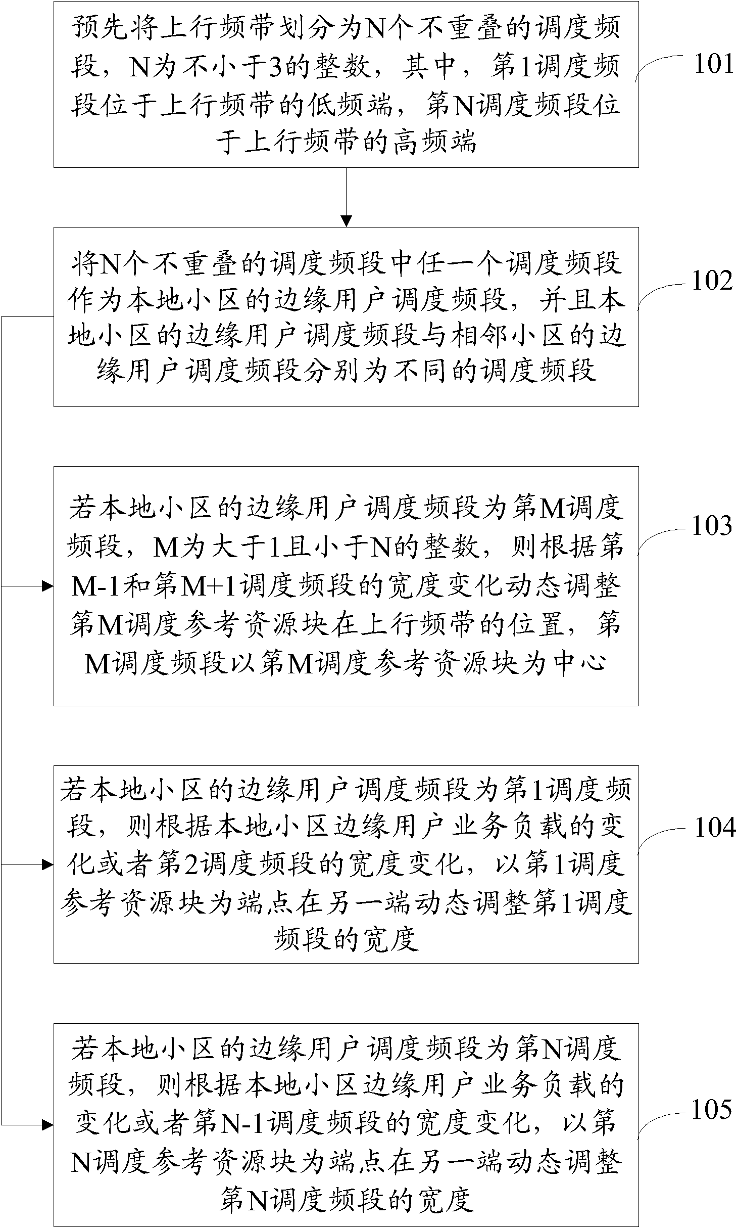
[0023] Please refer to figure 1 , an embodiment of the present invention provides a method for dynamically allocating uplink frequency band resources, the method comprising the following steps:

[0024] 101. Divide the uplink frequency band into N non-overlap...


PUM


Abstract

The invention discloses a dynamic distribution method of an uplink frequency band resource, comprising the following steps of: dividing an uplink frequency band into a plurality of non-overlapping dispatching frequency sections in advance; using one of the dispatching frequency sections as a cell-edge user dispatching frequency section of a local cell; configuring a dispatching reference resourceblock for each dispatching frequency section; and using the dispatching reference resource block as a reference dynamic state to regulate each dispatching frequency section. The embodiment of the invention also provides a corresponding base station. In the technical scheme of the invention, because the position of the dispatching frequency section positioned in the middle of the frequency band can be dynamically regulated, the width of the dispatching frequency section positioned at both ends of the uplink frequency band is only regulated at one end, therefore, the invention is capable of expanding the dynamic regulating amplitude of the dispatching frequency section, reducing the generation of resource fragments, effectively reducing same frequency interference among cells and increasinginterference coordination effect and resource utilization rate of the uplink frequency band.

Description

technical field [0001] The invention relates to the field of communication technology, in particular to a method for dynamically allocating uplink frequency band resources and a base station. Background technique [0002] The Long Term Evolution (LTE) system adopts Orthogonal Frequency Division Multiple Access (OFDMA) technology, so that users in the local cell do not interfere with each other, so that each cell can use the entire The frequency band resources of the system, but because of frequency reuse, it will inevitably cause inter-cell interference, especially for users who are located at the edge of the local cell and are relatively close to users at the edge of adjacent cells, the inter-cell performance will be greatly interfered. [0003] For the shared channel for transmitting data, Inter cell interference coordination (ICIC) technology can be used to reduce inter-cell interference and improve system performance by coordinating frequency band resource allocation and...

Claims


Application Information

Patent Timeline
Patent Type & Authority Applications(China)
IPC IPC(8): H04W16/10H04W72/12
Inventor 沈孝峰陈冰
Owner HUAWEI TECH CO LTD
Why Eureka
Try Eureka