
Plasma etching chamber

A plasma and corrosion chamber technology, applied in the field of ion corrosion chamber, can solve the problems of gas distribution plate pollution and other problems, and achieve the effect of reducing the amount of residues

Active Publication Date: 2010-10-06
SOSUL
View PDF0 Cites 0 Cited by
  • Summary
  • Abstract
  • Description
  • Claims
  • Application Information

AI Technical Summary

Problems solved by technology

[0010] In addition, conventional etch chambers have the problem that the edges of the gas distribution plate 14 can be contaminated by the plasma

Method used


Image

  • Plasma etching chamber
  • Plasma etching chamber
  • Plasma etching chamber

Examples


Embodiment Construction

[0030] Hereinafter, the plasma etching chamber will be described in detail with reference to the accompanying drawings.

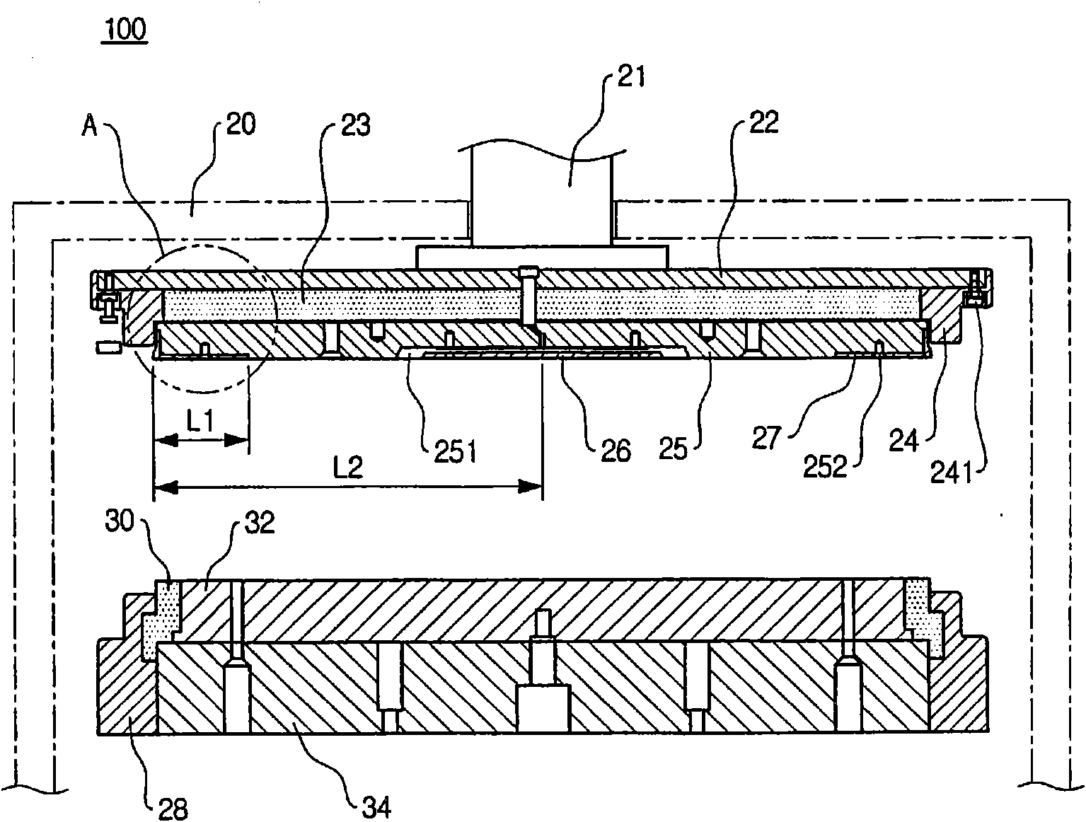
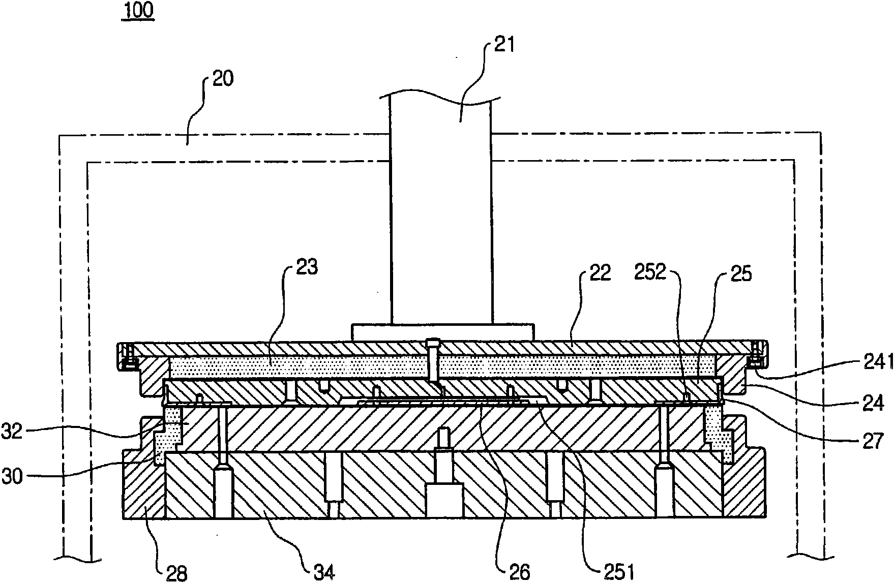
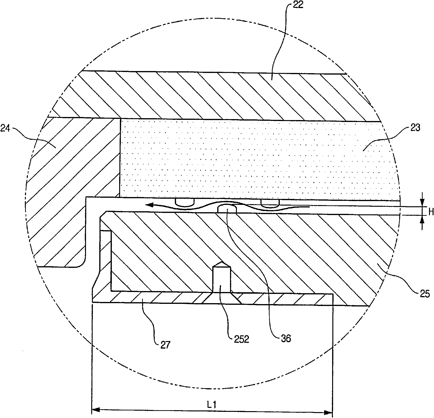
[0031] figure 1 is a partial cross-sectional view of the plasma etching chamber. figure 2 is a partial cross-sectional view of the plasma etch chamber after the moving rod is lowered. image 3 yes figure 1 Partial enlarged view of part A in the middle. Figure 4 is a schematic plan view of the gas distribution plate.

[0032] see figure 1 and 2 , the plasma etching chamber 100 includes a chamber wall 20 providing a space isolated from the outside thereof, a moving rod 21 operated by an actuator (not shown) when passing the upper part of the chamber wall 20, and a plate formed under the moving rod 21 . The plates include an upper plate 22 and a lower plate 23 .

[0033] The lower plate 23 is arranged under the bottom surface of the upper plate 22 , and the ring-shaped upper electrode 24 is arranged along the edge of the lower plate 23 . The uppe...


PUM


Abstract

Disclosed is a plasma etching chamber including a gas distribution plate guiding a reaction gas to the edge of the wafer; a plate disposed to be spaced apart from the gas distribution plate; and bumper portions protruding on at least one of opposite surfaces of the gas distribution plate and the plate to allow the pressure of the reaction gas moving to the edge of the wafer to be uniform.

Description

technical field [0001] Disclosed herein is a plasma etching chamber, and more particularly, one capable of removing, by plasma etching, a film remaining on the edge of a plasma dry etched wafer and particles deposited around the edge of the wafer. Background technique [0002] When a wafer is manufactured, thin films stacked in a pattern are generally formed over the entire surface of the wafer to the edge of the wafer. Here, the residue generated in the dry cleaning process of plasma etching the entire top surface of the wafer is not completely removed, but is deposited as particles on the entire top, side, and bottom surfaces of the wafer at the edge of the wafer. [0003] If the thin films and particles deposited at the edge of the wafer remain unremoved, serious damage can be caused to the semiconductor chip to be obtained. [0004] The plasma etching chamber is used to remove the film and particles remaining on the edge of the wafer. Figure 5 is a partial sectional vi...

Claims


Application Information

Patent Timeline
Patent Type & Authority Applications(China)
IPC IPC(8): H01L21/3065
CPCH01J2237/3343H01J37/3244H01L21/02087H01L21/3065
Inventor 李熙世郑成炫朴世文
Owner SOSUL
Learn More