
LED drive circuit and portable lamp

A technology of LED drive and circuit, applied in the direction of lamp circuit layout, electric light source, light source, etc., can solve problems such as inability to protect lamps

Inactive Publication Date: 2010-10-13
OCEANS KING LIGHTING SCI&TECH CO LTD +1
View PDF5 Cites 26 Cited by
  • Summary
  • Abstract
  • Description
  • Claims
  • Application Information

AI Technical Summary

Problems solved by technology

[0003] The purpose of the embodiments of the present invention is to provide an LED driving circuit, aiming to solve the problem that the existing LED driving circuit cannot effectively protect the lamps during short circuit in the constant current output circuit

Method used


Image

  • LED drive circuit and portable lamp
  • LED drive circuit and portable lamp
  • LED drive circuit and portable lamp

Examples


Embodiment Construction

[0014] In order to make the object, technical solution and advantages of the present invention clearer, the present invention will be further described in detail below in conjunction with the accompanying drawings and embodiments. It should be understood that the specific embodiments described here are only used to explain the present invention, not to limit the present invention.

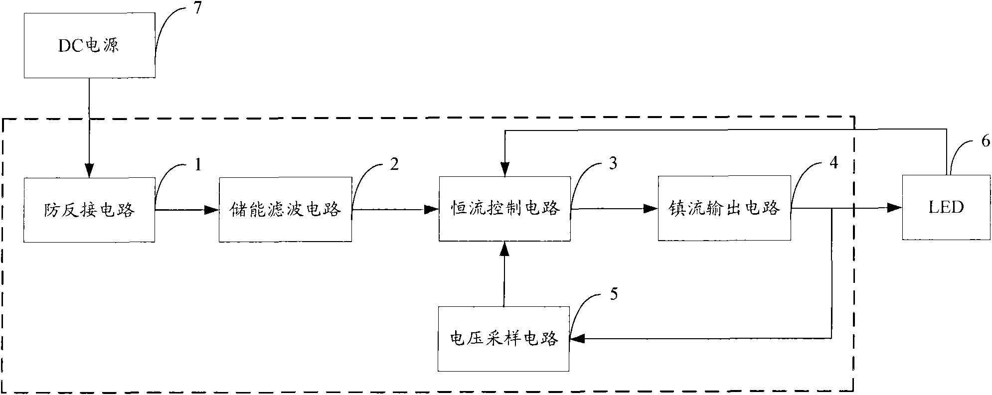
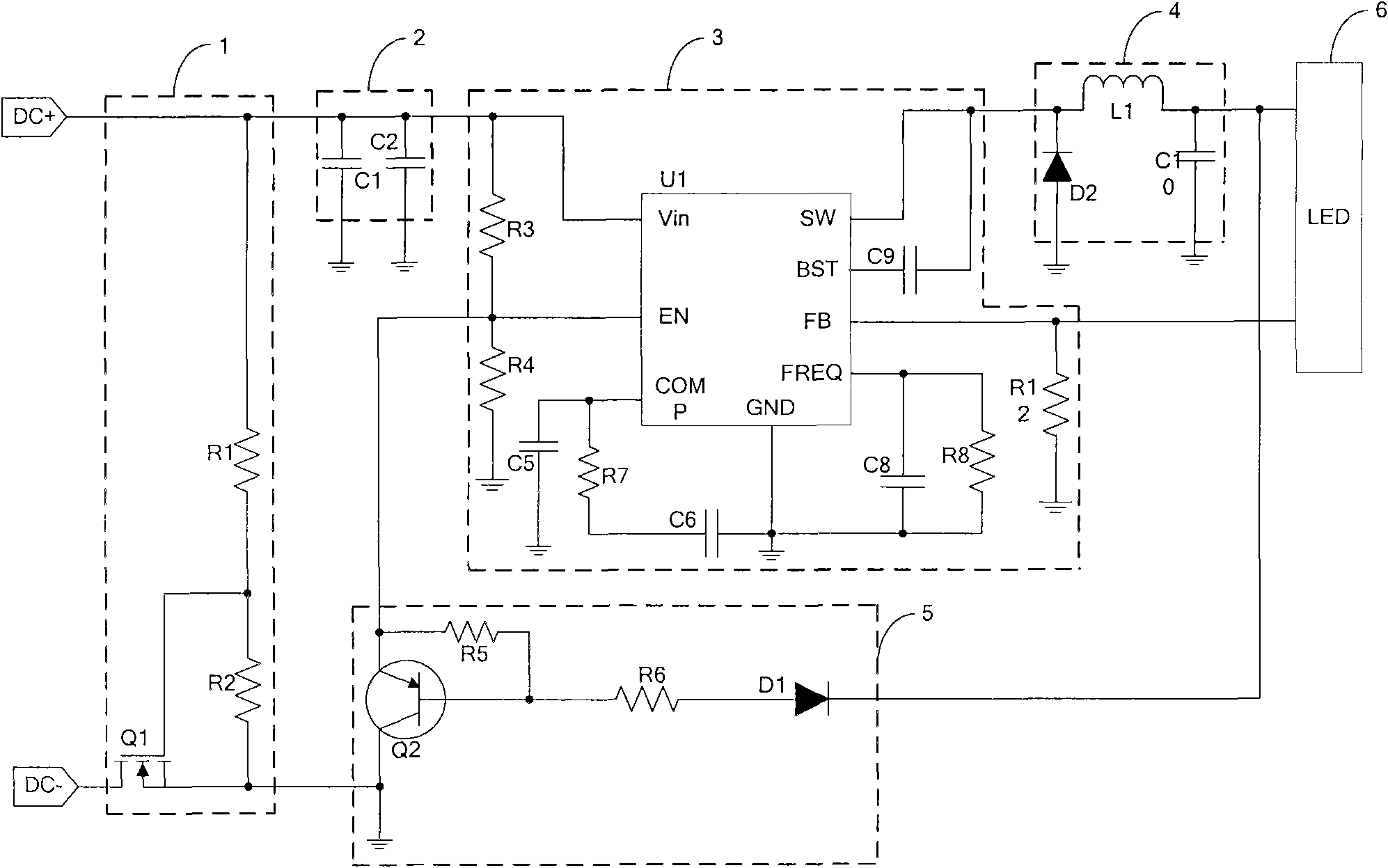
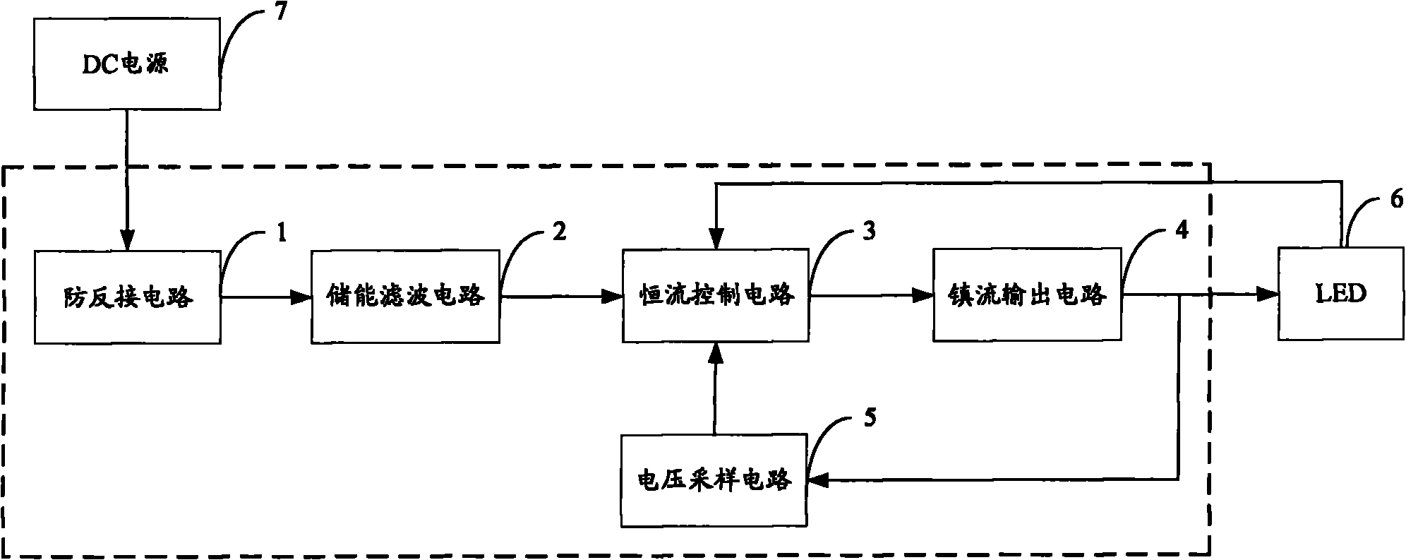
[0015] The LED drive circuit provided by the present invention uses a voltage sampling circuit to sample the working voltage of the LED. When the output is short-circuited, the voltage at the enable terminal of the constant current control circuit is pulled down by the conduction of the first switching element, and the constant current control circuit Shutdown the output, thereby acting as short-circuit protection.

[0016] The LED drive circuit provided by the embodiment of the present invention is mainly used in a potentiometer-type portable lamp with continuously adjustable brightness. The porta...


PUM


Abstract

The invention is applicable in the field of lamp illumination, and provides an LED drive circuit and a portable lamp. The LED drive circuit comprises a constant current control circuit, a ballast output circuit and a voltage sampling circuit; the voltage sampling circuit comprises a first switching element, a diode D1 and a current-limiting resistor R6; a control end of the first switching element is connected to the anode of the diode D1 through the current-limiting resistor R6, and the cathode of the diode D1 is connected to the output end of the ballast output circuit; the first end of the first switching element is connected with the enabling end of the constant current control circuit, and the second end is grounded; and when a short circuit is output, the first switching element is connected, the voltage of the enabling end of the constant current control circuit is dropped, and the constant current control circuit switches on or off the output. The LED drive circuit provided by the invention samples the working voltage of an LED by using the voltage sampling circuit; and when the short circuit is output, the voltage of the enabling end of the constant current control circuit is dropped through the connection of the first switching element, and the constant current control circuit switches on or off the output to play a role in short circuit protection.

Description

technical field [0001] The invention belongs to the field of lamp lighting, in particular to an LED driving circuit and a portable lamp. Background technique [0002] The existing short-circuit protection circuit adopts the current sampling method. When the output current is too large, the short-circuit protection circuit shuts off the output to protect the lamp; however, in the constant-current output circuit, the current and load are normal when the load is short-circuited. The current during operation is the same, so the above-mentioned current sampling method cannot protect the lamps during short circuit, and also causes waste of electric energy. Contents of the invention [0003] The purpose of the embodiment of the present invention is to provide an LED driving circuit, aiming at solving the problem that the existing LED driving circuit cannot effectively protect the lamp in the event of a short circuit in the constant current output circuit. [0004] The embodiment...

Claims


Application Information

Patent Timeline
Patent Type & Authority Applications(China)
IPC IPC(8): H05B37/02
Inventor 周明杰黄柯青
Owner OCEANS KING LIGHTING SCI&TECH CO LTD
Learn More