Gardening tool

A technology of garden tools and tool bars, which is applied in the direction of hand tools, etc., can solve the problems of large occupation and high manufacturing cost, and achieve the effect of reducing the storage space and reducing manufacturing cost

Inactive Publication Date: 2012-05-23
HANGZHOU GREAT STAR IND CO LTD
View PDF0 Cites 0 Cited by
  • Summary
  • Abstract
  • Description
  • Claims
  • Application Information

AI Technical Summary

Problems solved by technology

[0003] The technical problem to be solved and the technical task proposed by the present invention are to overcome the defects of high manufacturing cost of the existing one-piece structure garden tools and occupy a relatively large position during storage, and provide a garden tool with a handle and a head that can be quickly changed. To reduce manufacturing costs and reduce storage space

Method used


Image

  • Gardening tool
  • Gardening tool
  • Gardening tool

Examples


Embodiment 1

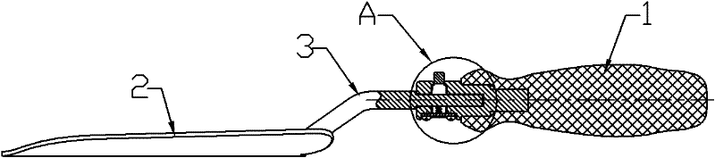
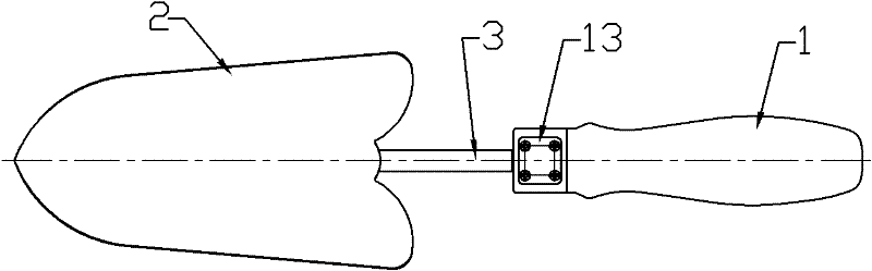
[0023] Such as Figure 1-3 As shown, the garden tool includes a handle 1 and a head 2, the head 2 has a tool bar 3 extending backward, the handle 1 is provided with a mounting hole 4, the tool bar 3 is inserted in the mounting hole 4 and the tool bar 3 is installed The hole 4 cooperates to prohibit the rotation of the tool bar 3 and affects the use. In this embodiment, a plane 6 is provided on the tool bar 3, and the mounting hole 4 is provided with a hole wall that matches the plane 6 of the tool bar. The plane 6 and the hole wall (generally, when the section of the tool bar 3 and the mounting hole 4 are circular, the tool bar is easy to rotate in the mounting hole, so when the section of the tool bar 3 and the mounting hole 4 is limited to a non-circular When round, such as ellipse, triangle, square, etc., you can also set keys and keyways on the tool bar and the mounting hole respectively, so that the tool bar can be prohibited from rotating); in addition, the handle 1 is p...

Embodiment 2

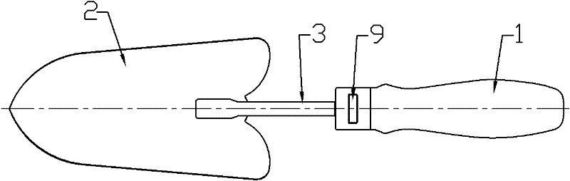
[0026] The example is Figure 7-9 As shown, the locking and unlocking of the locking part by the locking assembly is realized according to the following structure (other structures are the same as in Embodiment 1, and will not be described in detail): the locking part is the surface of the tool bar, and the locking assembly includes a The push button 15 on the handle 1, the lock sleeve 16 pushed by the push knob 15 and the elastic element 17 (spring) supporting the lock sleeve 16, the tool bar 3 is inserted in the lock sleeve 16 and locked by the elastic element 17 Cover 16 is inclined to support so that locking sleeve 16 is stuck on the surface of tool bar so as to Figure 8 Lock the tool bar in the mounting hole as shown. Generally, the surface of the tool bar 3 is a plane or a wave-like undulating surface.

[0027] This example, when replacement is required, such as Figure 9 As shown, push the push button 15 to the right by hand, and the locking sleeve 16 will be straig...

Embodiment 3

[0029] The example is Figure 10-12 As shown, the locking and unlocking of the locking part is realized by the locking assembly according to the following structure (other structures are the same as in Embodiment 1, and will not be described in detail): the locking part is a recess 18 provided on the tool bar 3 (such as Ring groove, pit, etc.), the locking assembly includes a locking sleeve 19 that is threaded on the handle 1 and a locking pin 20 that is placed in the corresponding recess on the handle 1. The locking sleeve 19 has the function of pressing the locking pin 20 in the concave portion Bevel 21 in 18. The locking pin 20 is supported by the elastic element and disengages from the recess 18 on the tool bar so that the working bar is pulled out from the installation hole when unlocking (the assembly relationship between the lock pin and the elastic element can be like the assembly relationship between the button and the elastic element in Embodiment 1).

[0030] Such ...


PUM


Abstract

The invention discloses a gardening tool. A conventional gardening tool with an integral structure has high manufacturing cost and occupies large position during storage. The gardening tool comprises a handle and a head, wherein the head is provided with a tool bar extended backwards; the gardening tool is characterized in that the handle is provided with a mounting hole; the tool bar is insertedinto the mounting hole and matched with the mounting hole to prevent the rotation of the tool bar; the handle is provided with a locking component; and the part of the tool bar inserted into the mounting hole is provided with a locking part which is locked and unlocked by the locking component. The gardening tool prevents the rotation of the tool bar by forming the mounting hole on the handle andinserting the tool bar of the head into the mounting hole; the locking component and the locking part are arranged on the handle and the tool bar respectively and matched with each other for locking and unlocking; thus, split arrangement and rapid disassembling of the head and the handle are realized; and one handle can be provided for a plurality of heads, so that the manufacturing cost is lowered and the position occupied by the storage is reduced.

Description

technical field [0001] The invention relates to a tool, in particular to a garden tool whose handle and head can be changed quickly. Background technique [0002] In the existing garden tools, the handle and the head are usually connected as a whole, and each garden tool must be equipped with a handle, which is expensive to manufacture and takes up a large space when stored. Contents of the invention [0003] The technical problem to be solved and the technical task proposed by the present invention are to overcome the defects of high manufacturing cost of the existing one-piece structure garden tools and occupy a relatively large position during storage, and provide a garden tool with a handle and a head that can be quickly changed. It is used to reduce the manufacturing cost and reduce the space occupied by storage. For this reason, the present invention adopts following technical scheme: [0004] The garden tool includes a handle and a head, and the head has a tool ro...

Claims


Application Information

Patent Timeline
Patent Type & Authority Patents(China)
IPC IPC(8): A01B1/22
Inventor 仇建平
Owner HANGZHOU GREAT STAR IND CO LTD
Why Eureka
Try Eureka