Movable windbreak for bridge

A technology for bridges and wind barriers, applied in the direction of bridges, bridge parts, bridge construction, etc., can solve the problems of increasing the wind resistance coefficient of the main structure of the bridge, increasing the investment cost of the bridge, and increasing the difficulty of design, and achieves clear movements and deformation. Small and easy to maintain

Active Publication Date: 2010-10-20
CCCC HIGHWAY CONSULTANTS +1
View PDF0 Cites 16 Cited by
  • Summary
  • Abstract
  • Description
  • Claims
  • Application Information

AI Technical Summary

Problems solved by technology

However, the installation of wind barriers also increases the drag coefficient of the main structure of the bridge. Especially for super-long-span bridges, the scale of the main structure will inevitably increase accordingly, and the design difficulty will also increase accordingly, eventually leading to Increased bridge investment costs

Method used


Image

  • Movable windbreak for bridge
  • Movable windbreak for bridge
  • Movable windbreak for bridge

Examples


Embodiment

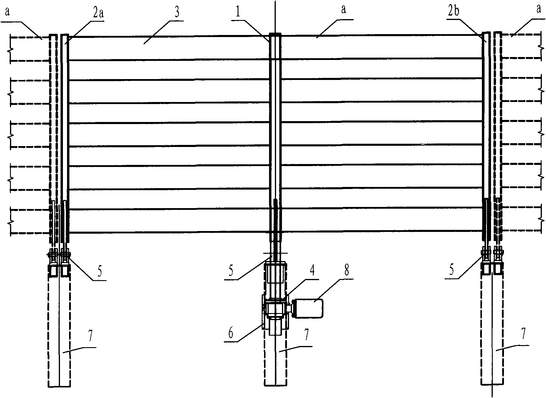
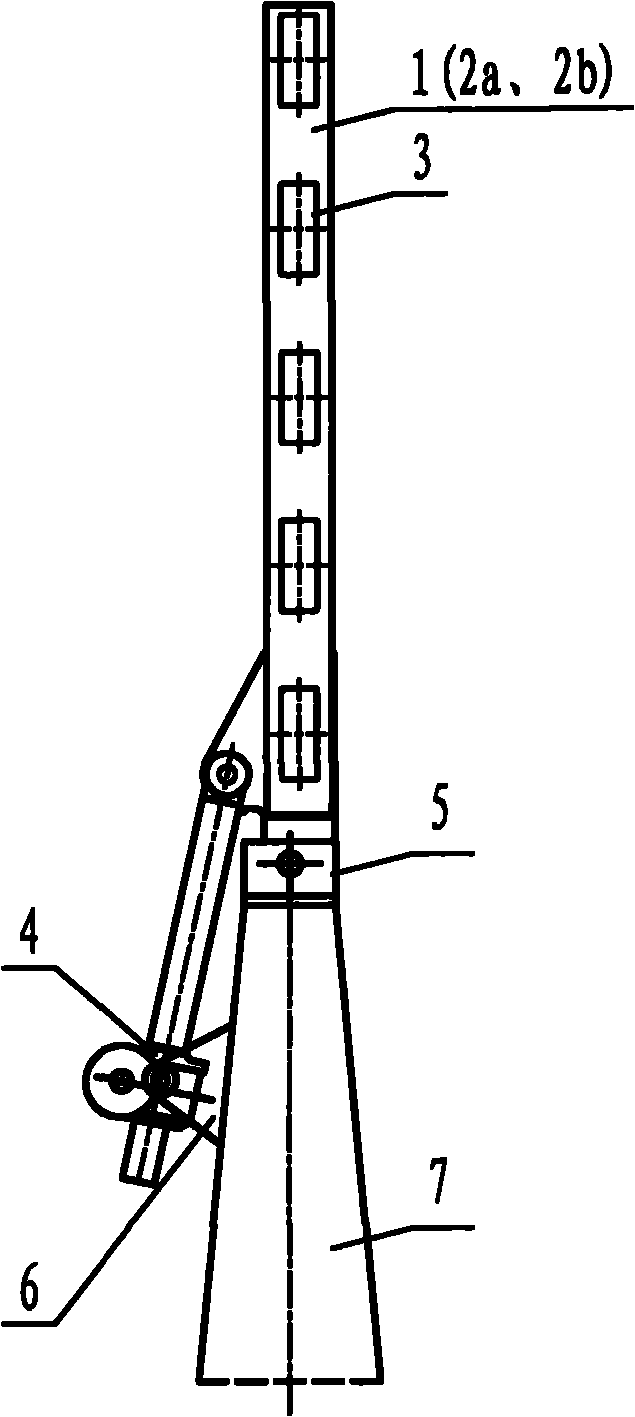
[0029] Such as figure 2 As shown, the movable wind barrier for the bridge of the present invention, a movable wind barrier unit a is made up of a movable wind barrier surface, a special driving mechanism 4, a support, and a base 7. The movable wind barrier surface is composed of a central column 1, two side columns 2a, 2b, and a plurality of wind barrier strips 3. Multiple wind barrier strips 3 are arranged horizontally, and the distance between adjacent wind barrier strips 3 is determined as required. The two ends of each wind barrier strip 3 are respectively fixed on the side columns 2a, 2b, and the central part of each wind barrier strip 3 is fixed on the center column 1 to form a complete wind barrier surface. The lower ends of the central column 1 and both sides of the columns 2a and 2b stretch out a proper distance from the lower edge of the wind barrier surface. The transverse hinged holes at the lower ends of the central column 1 and both side columns 2a and 2b are ...


PUM


Abstract

The invention discloses a movable windbreak for a bridge, and relates to a bridge technology. The movable windbreak comprises a plurality of movable windbreak units which are sequentially and linearly arranged along the bridge towards both sides of the bridge floor, wherein each movable windbreak unit comprises a movable windbreak face, a special driving mechanism, a bracket and a base. The movable windbreak for the bridge can effectively ensure the driving safety on the bridge under crosswind conditions, raise the ambient wind speed for driving on the bridge, effectively ensure the wind resistance safety of a major bridge structure after the windbreak is arranged, and effectively lower the cost of the major bridge structure in the aspect of wind resistance design.

Description

technical field [0001] The invention relates to the technical field of bridges, and relates to a movable wind barrier for bridges. Background technique [0002] "Code for Wind Resistance Design of Highway Bridges" puts a limit on the driving wind speed of the bridge deck. When the wind speed of the bridge deck exceeds this value, traffic control is generally required on the bridge deck for the sake of driving safety. If the wind environment of the bridge site is bad, it will inevitably affect the traffic rate of the bridge, and then affect the economic and social benefits of the bridge. [0003] In order to ensure the safety of crosswind driving on the bridge deck and improve the wind speed of the driving environment on the bridge, the conventional method is to set up wind barriers. However, setting up wind barriers also increases the drag coefficient of the main structure of the bridge, especially for super-long-span bridges, the scale of the main structure will inevitably...

Claims


Application Information

Patent Timeline
Patent Type & Authority Applications(China)
IPC IPC(8): E01F7/02E01D19/00
Inventor 宋晖郝海龙孟凡超周山水张克王晓冬
Owner CCCC HIGHWAY CONSULTANTS
Why Eureka
Try Eureka