Double clutch transmission

A dual-clutch and transmission technology, applied in vehicle gearboxes, transmissions, transportation and packaging, etc., can solve problems such as structural length extension

Inactive Publication Date: 2010-10-20
ZF FRIEDRICHSHAFEN AG
View PDF10 Cites 7 Cited by
  • Summary
  • Abstract
  • Description
  • Claims
  • Application Information

AI Technical Summary

Problems solved by technology

This leads to an undesired extension of the structural length in the axial direction

Method used


Image

  • Double clutch transmission
  • Double clutch transmission
  • Double clutch transmission

Examples


Embodiment Construction

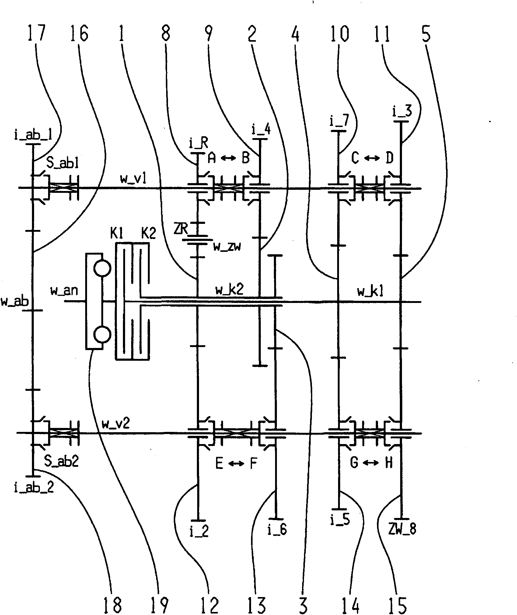
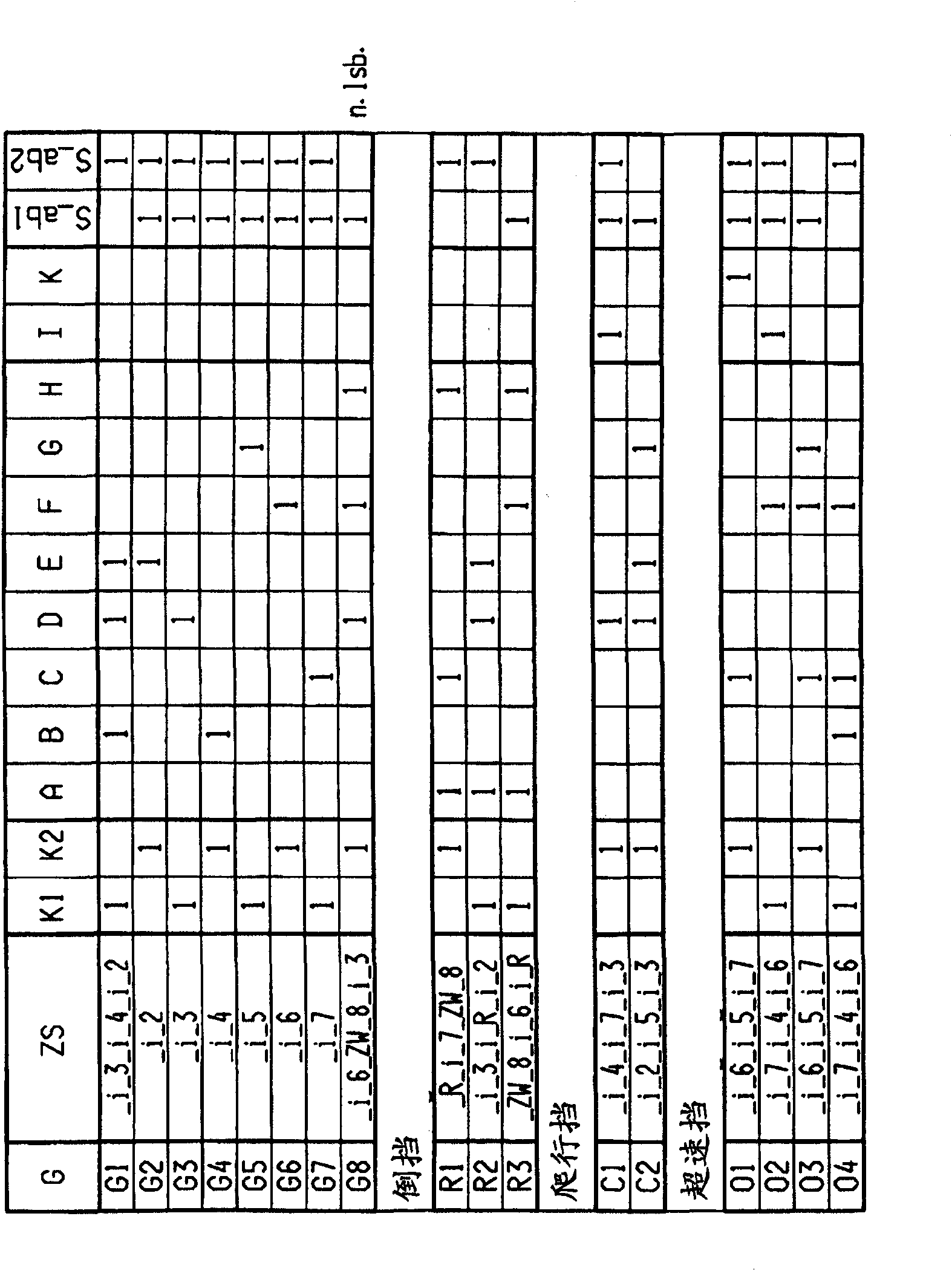
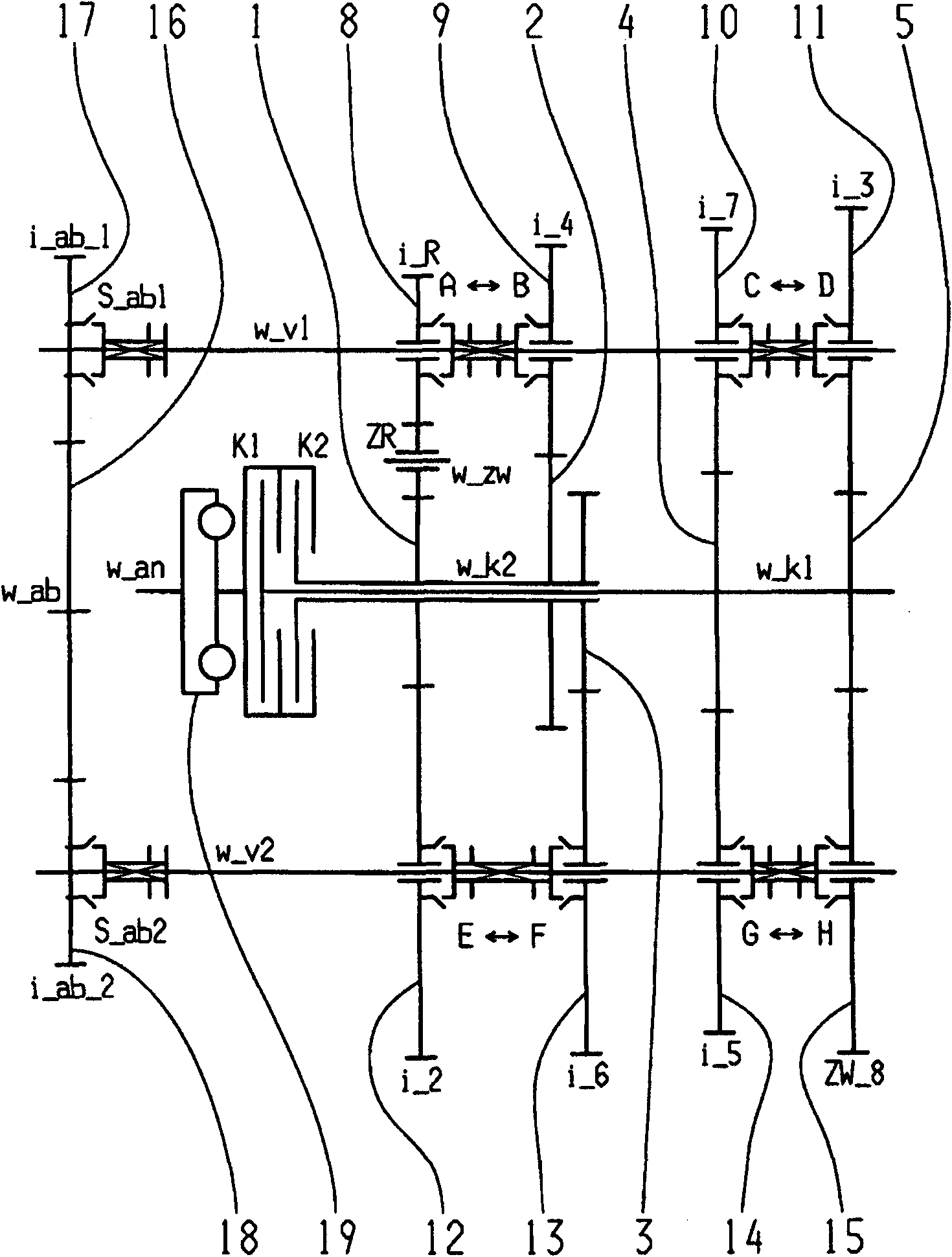
[0047] exist figure 1 , 3 , 5, 7, 9, 11 and 13 respectively show possible implementations of the eight-speed dual clutch transmission. The corresponding shift diagrams for different implementations are in figure 2 , 4 , 6, 8, 10, 12 and 14 are represented graphically.

[0048] The eight-speed dual-clutch transmission comprises two clutches K1, K2, the input side of which is connected to the drive shaft w_an and the output side of which is connected to one of two transmission input shafts w_k1, w_k2 arranged coaxially with each other. . Furthermore, a torsional vibration damper 19 can be arranged on the drive shaft w_an. In addition, two countershafts w_v1 , w_v2 are provided, on which gearwheels in the form of idler gears 8 , 9 , 10 , 11 , 12 , 13 , 14 , 15 are rotatably mounted. On the two transmission input shafts w_k1 , w_k2 , gearwheels in the form of fixed gearwheels 1 , 2 , 3 , 4 , 5 are arranged in a rotationally fixed manner, said fixed gearwheels being at least...


PUM


Abstract

A double clutch transmission with two clutches whose input sides are connected to a drive shaft and whose output sides are each connected to one of two transmission input shafts positioned coaxial with respect to one another. At least two countershafts provided and support toothed idler gearwheels while the two transmission input shafts support toothed fixed gearwheels such that it is possible toshift at least a plurality of power shift forward gears and / or at least one reverse gear. Five gear planes are provided so that at least one winding path gear is shiftable when at least one coupling device, assigned to the output gear, is disengaged.

Description

technical field [0001] The invention relates to a dual clutch transmission of the type specified in the preamble of claim 1 . Background technique [0002] A six-speed or seven-speed dual clutch transmission is known from DE 10305241 A1. The dual clutch transmission comprises two clutches which are each connected with their input sides to a drive shaft and with their output sides to each of the two transmission input shafts. The two transmission input shafts are arranged coaxially with each other. The other two countershafts are arranged with axes parallel to the two transmission input shafts, and the idler gears of the two countershafts mesh with the fixed gears of the transmission input shafts. In addition, the coupling device is fastened in an axially displaceable, rotationally fixed manner on the countershaft in order to be able to engage the corresponding gearwheel. The correspondingly selected transmission ratio is transmitted to the differential via the output gear...

Claims


Application Information

Patent Timeline
Patent Type & Authority Applications(China)
IPC IPC(8): F16H3/08
CPCF16H2200/0065F16H2003/0826F16H2200/0091F16H2200/0026F16H2003/0931F16H3/006F16H2200/006F16H2200/0086F16H2200/0095Y10T74/19223
Inventor W·里格尔M·赖施J·瓦夫齐希G·贡波尔茨贝格
Owner ZF FRIEDRICHSHAFEN AG
Why Eureka
Try Eureka