Lens matched with high-power LED lamp

An LED lamp, high-power technology, applied in the parts of lighting devices, semiconductor devices of light-emitting elements, lighting devices, etc., can solve problems such as affecting light transmittance, yellowing, zebra crossing or light waste, and avoid zebra patterns. , the effect of saving energy and beautifying the urban environment

Inactive Publication Date: 2013-05-01
HEBEI KINGDOM PHOTOVOLTAIC TECH
View PDF0 Cites 2 Cited by
  • Summary
  • Abstract
  • Description
  • Claims
  • Application Information

AI Technical Summary

Problems solved by technology

[0002] For high-power LEDs, the directionality of light emission is very strong. The general package is to add a lens to form a light distribution after implanting a chip on a heat sink. The light output angle can be between 30 degrees and 170 degrees. Adjustable, this kind of light distribution is called Brown type (water drop type) light distribution. The light spot formed on the ground is approximately circular, and it is a light spot with the highest brightness in the center and a decreasing trend towards the edge. If the secondary light distribution is considered, a circular light spot will be formed after the street lamp hits the road surface. For road conditions, it is generally long vertically and narrow horizontally, which belongs to a rectangular range, so it will cause zebra crossing or light waste. The secondary light distribution also needs to consider the issue of uniformity, so the light distribution is also critical
At present, the batwing light distribution lens made of acrylic is generally used, but its uniformity cannot meet the national standard after measurement, and the anti-ultraviolet ability of acrylic is relatively weak, and it will turn yellow after a few months of ultraviolet irradiation. , affecting the light transmittance
For the occurrence of the above problems, the prior art does not have a good solution, which brings inconvenience to the work in this field

Method used


Image

  • Lens matched with high-power LED lamp
  • Lens matched with high-power LED lamp
  • Lens matched with high-power LED lamp

Examples


Embodiment Construction

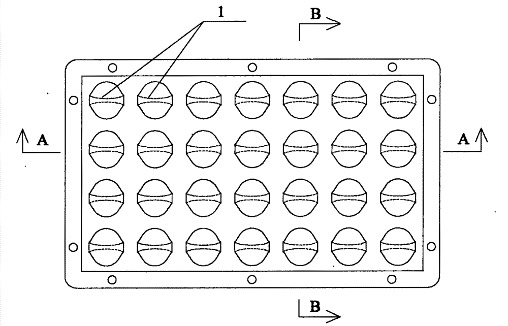
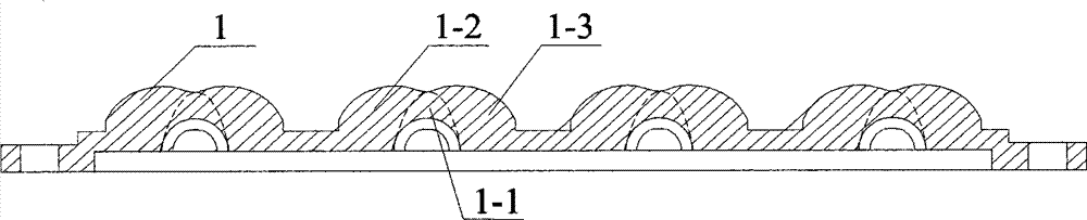
[0013] Referring to the accompanying drawings, it is a lens matched with a high-power LED lamp. The lens structure includes a lens unit 1 matched with the basic light-emitting unit of the LED lamp. The above-mentioned lens unit 1 is composed of a cylindrical convex lens 1-1 and two symmetrical A composite structure composed of spherical convex lenses 1-2 and 1-3 distributed on both sides of the cylindrical convex lens 1-1.

[0014] The spherical centers of the above two spherical convex lenses 1-2, 1-3 are arranged symmetrically on the mid-perpendicular of the axis of the cylindrical convex lens 1-1.

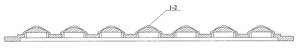
[0015] The inner surface of the above-mentioned cylindrical convex lens 1-1 is an arc cylindrical structure, and the outer surface is an arc spherical structure. The intersecting lines form a composite light emitting surface.

[0016] The spherical convex lenses 1-2 and 1-3 mentioned above are entities of a partial sphere whose outer surface is a spherical surface.

[0017] Th...


PUM


Abstract

The invention discloses a lens matched with a high-power LED lamp, which solves the technical problems that the emergent light intensity and uniformity of the lens do not accord with the national arterial traffic standard and the lens is easy to age. The invention adopts the technical scheme that the structure of the lens matched with the high-power LED lamp comprises a lens monomer matched with a basic luminous unit of the LED lamp, and the lens monomer has a composite structure consisting of a cylindrical convex lens and two spherical convex lenses symmetrically distributed on two sides of the cylindrical convex lens. The lens has the advantages of limiting the divergence range of a light source and a ground light spot shape by redesigning and combining the geometric shape of the lens monomer, avoiding the occurrence of zebra stripes on a road, reaching strongest illumination in the state specified illumination range of the single lens monomer, solving the problem puzzling researchers for long time, beautifying the urban environment and saving energy to a certain degree.

Description

technical field [0001] The invention relates to a lens matched with a high-power LED lamp, which belongs to the field of high-power LED street lamp lighting, in particular to a composite optical lens capable of achieving the strongest illumination within the lighting range of a single lens unit specified by the state. Background technique [0002] For high-power LEDs, the directionality of light emission is very strong. The general package is to add a lens to form a light distribution after implanting a chip on a heat sink. The light output angle can be between 30 degrees and 170 degrees. Adjustable, this kind of light distribution is called Brown type (water drop type) light distribution. The light spot formed on the ground is approximately circular, and it is a light spot with the highest brightness in the center and a decreasing trend towards the edge. If the secondary light distribution is considered, a circular light spot will be formed after the street lamp hits the ro...

Claims


Application Information

Patent Timeline
Patent Type & Authority Patents(China)
IPC IPC(8): F21V5/04F21Y101/02
CPCF21Y2101/02F21W2131/103F21V5/04F21Y2115/10
Inventor 徐峰献孙占宁
Owner HEBEI KINGDOM PHOTOVOLTAIC TECH
Why Eureka
Try Eureka