Strapping unit and method

A technology of binding device and working position, which is applied in the direction of binding materials, parts of binding machinery, paper/cardboard containers, etc., to achieve the effect of compact design and reduced quantity

Active Publication Date: 2010-10-27
SUND BIRSTA
View PDF10 Cites 25 Cited by
  • Summary
  • Abstract
  • Description
  • Claims
  • Application Information

AI Technical Summary

Problems solved by technology

A disadvantage of these known strapping devices is that the sealless joint they form in the overlap at the ends of the meta

Method used


Image

  • Strapping unit and method
  • Strapping unit and method
  • Strapping unit and method

Examples


Embodiment Construction

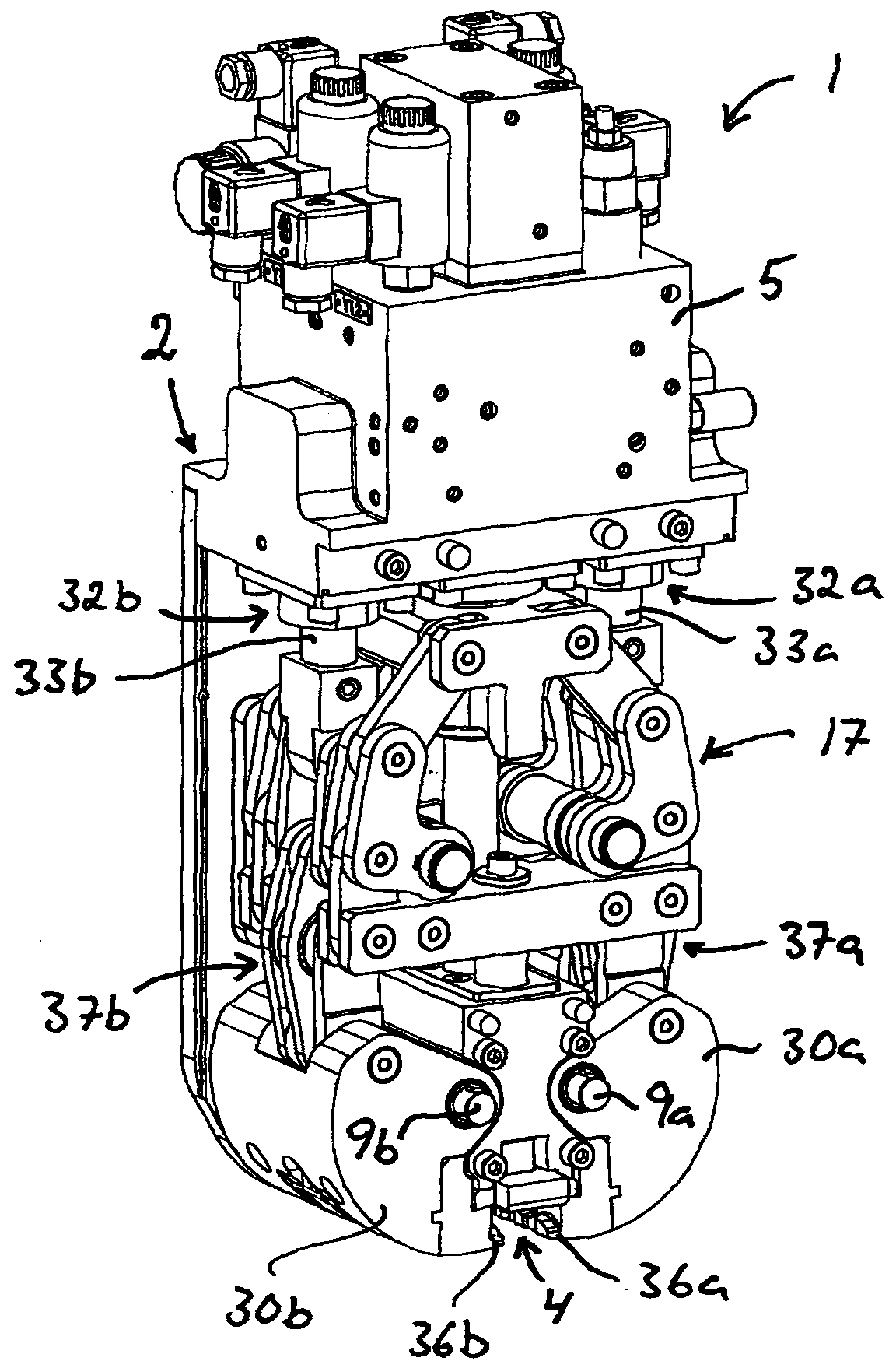
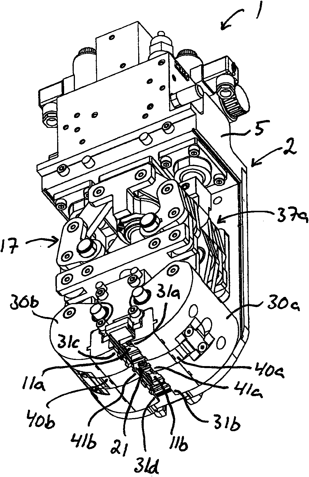
[0043] figure 1 and 2 A strapping device for forming a sealless joint in an overlap at the ends of a loop of metal strap is shown in accordance with an embodiment of the invention. The strapping device is shown here without a protective cover that would cover the central portion of the strapping device to protect the mechanisms contained therein.

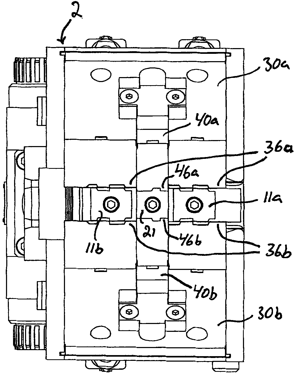
[0044] The strapping device 1 comprises a housing 2 . Main punch seat 10 (see Figure 3c ) is movably mounted in the housing 2 and carries a number of stamped parts 11a, 11b. In the illustrated embodiment, the two main stamping parts 11a, 11b are detachably mounted on the main punch holder 10 by means of screws or similar fastening elements, so that the corresponding main stamping parts can be replaced. By means of the first punch actuator, the main punching parts 11a, 11b can be brought together with the main punch holder 10 in the retracted position (see Figure 3c ) and feed stamping position (see Figure 5c ) to move back ...


PUM


Abstract

A strapping unit (1) comprising main punch members (11a, 11b), a security punch member (21), main die members (31a-d) forming a first and a second main jaw and security die members (41a, 41b) forming a first and a second auxiliary jaw. The punch members are displaceable to and fro between a retracted position and an advanced punching position. The jaws are moveable towards and away from each other between a retracted open position and an advanced active position, and the auxiliary jaws are moveable in relation to the main jaws. The main die members and the main punch members are arranged to co-operate so as to cut mutually interlocking incisions in overlapping portions at the ends of a loop of metal strap received in the strapping unit. The security die members and the security punch member are arranged to co-operate so as to cut security incisions in said overlapping metal strap portions.

Description

technical field [0001] The invention relates to a strapping device according to the preamble of claim 1 and to a method for forming a sealless joint in an overlap at the ends of a metal strap loop by means of such a strapping device Methods. Background technique [0002] A strapping device according to the preamble of claim 1 is known from US4154158A, US3794086A and GB2040825A. A disadvantage of these known strapping devices is that the sealless joint they form in the overlap at the ends of the metal strap loops only compresses the overlap in one direction under tension in the loop. The metal strap parts lock each other. If the tension in the loop is released, the sealless joint will thereby break and the overlapping metal strip portions will in turn loosen from each other. Contents of the invention [0003] The object of the present invention is to achieve a further development of a strapping device of the type according to the preamble of claim 1 in order to overcome ...

Claims


Application Information

Patent Timeline
IPC IPC(8): B65B13/04B65B13/18
CPCB65B13/30
Inventor L·尼尔森
Owner SUND BIRSTA
Why Eureka
Try Eureka