Electrical connector and method for making the same

An electrical connector and connecting part technology, which is applied in the direction of connection, two-part connecting device, and components of the connecting device, etc., can solve the problems of unreliable coordination, complicated assembly of the electrical connector, and increased production cost of the electrical connector, etc. Achieve the effect of saving production cost, good contact and ensuring coupling effect

Inactive Publication Date: 2010-10-27
FOXCONN (KUNSHAN) COMPUTER CONNECTOR CO LTD +1
View PDF5 Cites 4 Cited by
  • Summary
  • Abstract
  • Description
  • Claims
  • Application Information

AI Technical Summary

Problems solved by technology

[0003] Providing two circuit boards will increase the production cost of the electrical connector and complicate the assembly of the electrical connector
In addition, the connection part of the conductive path is attached to the selected terminal, which may easily lead to unreliable cooperation between it and the selected terminal, thereby affecting the coupling effect between the fixed terminal and the selected terminal.

Method used


Image

  • Electrical connector and method for making the same
  • Electrical connector and method for making the same
  • Electrical connector and method for making the same

Examples


Embodiment Construction

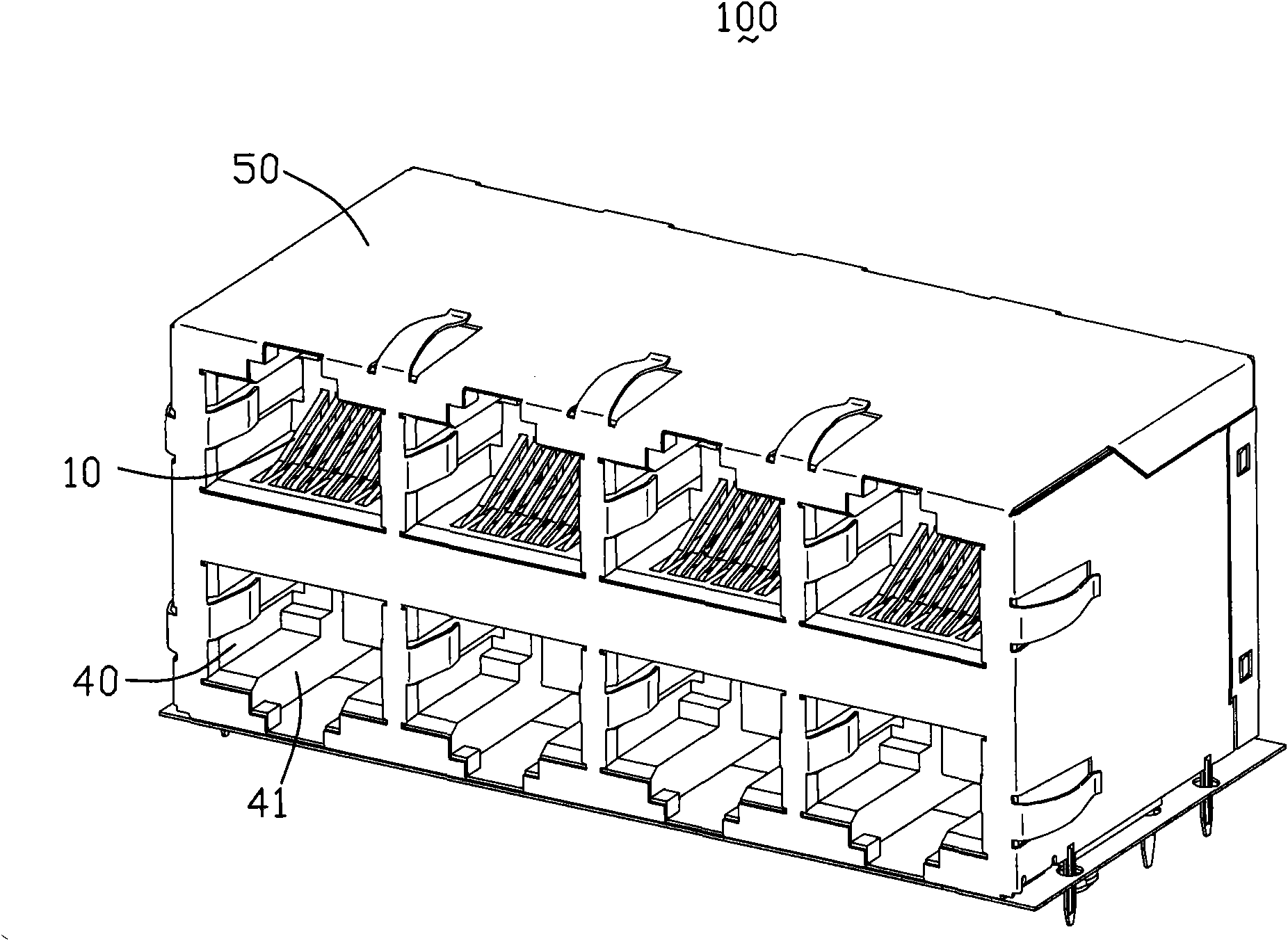
[0018] Such as figure 1 As shown, the electrical connector 100 according to the first embodiment of the present invention includes an insulating body 40 with a plurality of receiving cavities 41, a plurality of terminal modules 10 accommodated in the receiving cavities 41, and a shield covering the insulating body 40. Body 50. In other embodiments, the insulating body 40 can also be configured as a single interface.

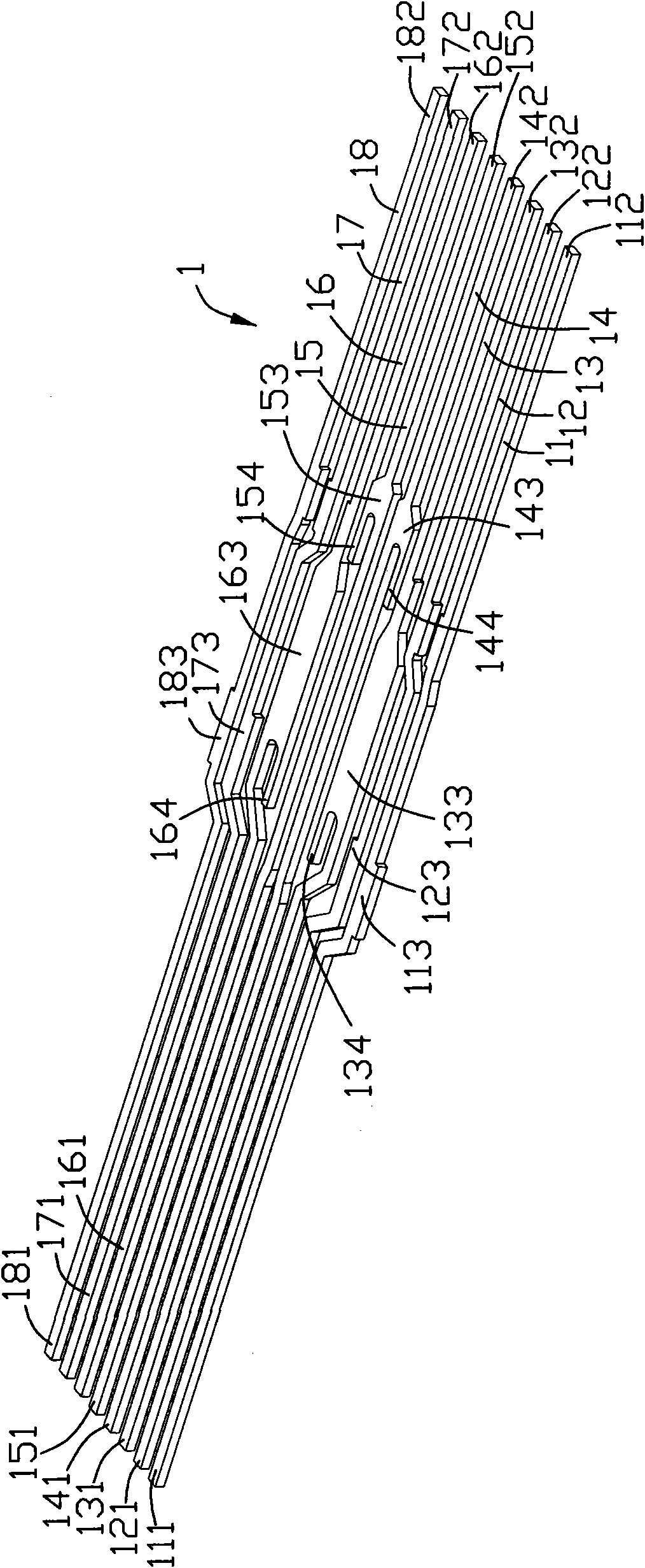
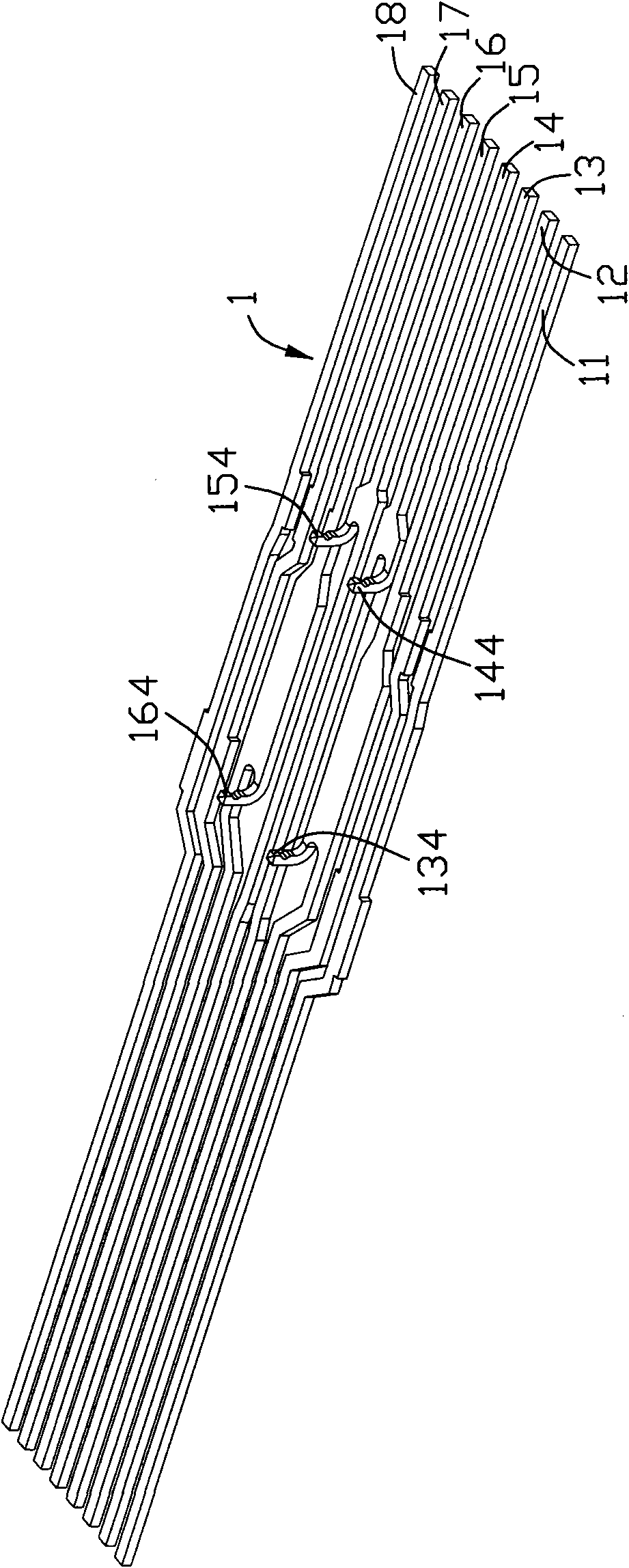
[0019] refer to Figure 4 to Figure 6 , each terminal module 10 includes an insulating sheet 2 , a plurality of terminals 1 and a metal sheet 3 . The terminals 1 are the first to eighth terminals 11-18 in this embodiment. The first to eighth terminals 11 - 18 are configured in the insulating sheet 2 by insert molding. Among them, the first and second terminals 11 and 12 are differential signal terminal pairs; the third and sixth terminals 13 and 16 are differential signal terminal pairs; the fourth and fifth terminals 14 and 15 are differential signal termina...


PUM


Abstract

An electrical connector includes an insulated body and a terminal module contained in the insulated body. The terminal module includes an insulated sheet, a plurality terminals contained within the insulated sheet and a metal sheet disposed on surface of the insulated sheet. The terminals have selected terminals and predefined terminals having coupling parts, the metal sheet comprises a plurality of conductive paths extending along a first plane in parallel with the insulated sheet plane. Each conductive path has a main body part flushed with the selected terminal and a connection part extending from the main body part to the predefined terminal. The terminals extend along the second plane in parallel with the first plane, wherein, the coupling parts of the predefined terminals are connected with conductive paths from the second plane to the connection direction close to the first plane. A making method of the electrical connector comprises holding the terminals in the insulated sheet; arranging the conductive paths on the surface of the insulated sheet, and enabling the conductive paths to be flushed with parts of terminals.

Description

【Technical field】 [0001] The invention relates to an electrical connector and its manufacturing method, in particular to a module connector capable of compensation between terminals and its manufacturing method. 【Background technique】 [0002] Please refer to US Patent No. 6,447,341 published on September 10, 2002 for prior art related to the present invention. This patent discloses a module connector, which includes a body part and a terminal module accommodated in the body part. The terminal module includes a pair of chips, a number of conductive paths arranged on the inner surface of the chips, and a number of terminals arranged between the pair of chips. One of the conductive paths has a first main body and a connecting portion. The main body portion of the conductive path is aligned with a fixed terminal among the plurality of conductive terminals, and the connecting portion is attached to a selected terminal among the plurality of conductive terminals, thereby establ...

Claims


Application Information

Patent Timeline
Patent Type & Authority Applications(China)
IPC IPC(8): H01R13/66H01R13/518H01R13/648H01R43/20
CPCH01R23/025Y10S439/941H01R24/64
Inventor 托德·M·哈兰特伦斯·F·李托
Owner FOXCONN (KUNSHAN) COMPUTER CONNECTOR CO LTD
Why Eureka
Try Eureka