Drag-reducing device of anti-rolling fin of ship wing flap

A technology of fin stabilizers and flaps, which is applied in the direction of using hydrofoils to reduce the movement of ships on the surrounding water surface, and can solve the problems of endangering the safety of ship navigation, reducing the effect of fin stabilizers and failing to reduce induced resistance, etc. To achieve the effect of preventing cavitation of water flow medium, improving anti-rolling effect, improving safety and economy

Inactive Publication Date: 2010-11-10
HARBIN ENG UNIV
View PDF6 Cites 21 Cited by
  • Summary
  • Abstract
  • Description
  • Claims
  • Application Information

AI Technical Summary

Problems solved by technology

The higher the speed of the vortex, the generated low pressure may reach the cavitation of the liquid (that is, cavitation occurs), resulting in a decrease in the lift of the fin stabilizer, and it will cause erosion and noise on the fin surface, reducing the stabilization of the fin stabilizer effect, endangering the safety of the ship's navigation
[0003] In order to improve the anti-rolling effect of the fin stabilizer, the fin stabilizer is designed to have a flap structure. Due to the function of the flap, the lift of the flap stabilizer fin is greater than that of the ordinary fin stabilizer, but this type The structure fails to reduce the induced drag caused by the wingtip vortex. "Induced drag" is an important part of the drag on the ship's fin stabilizer and is the main factor affecting the performance of the fin stabilizer

Method used


Image

  • Drag-reducing device of anti-rolling fin of ship wing flap
  • Drag-reducing device of anti-rolling fin of ship wing flap
  • Drag-reducing device of anti-rolling fin of ship wing flap

Examples


Embodiment Construction

[0015] The present invention is described in more detail below in conjunction with accompanying drawing example:

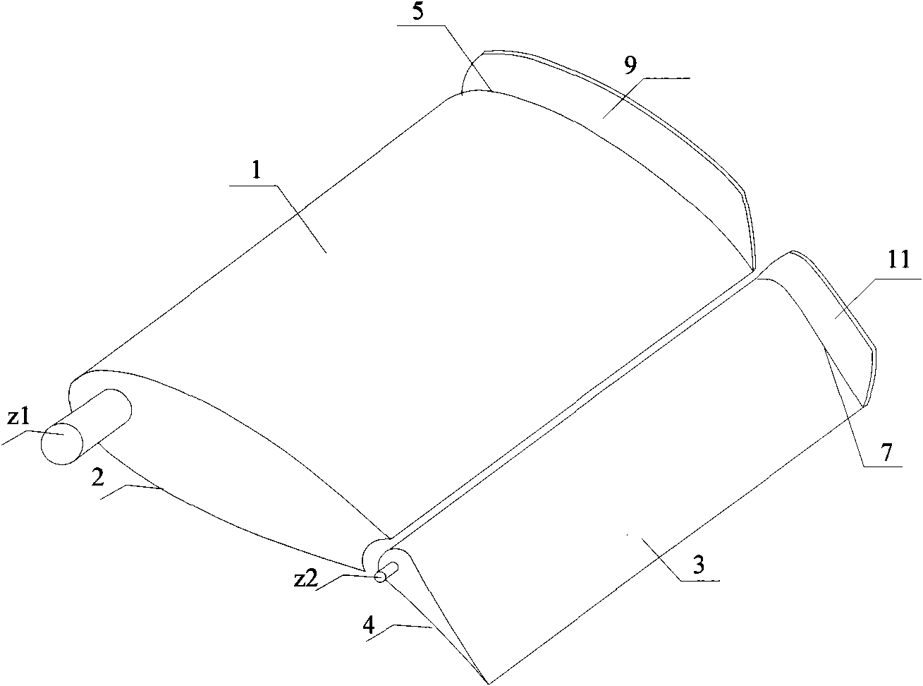
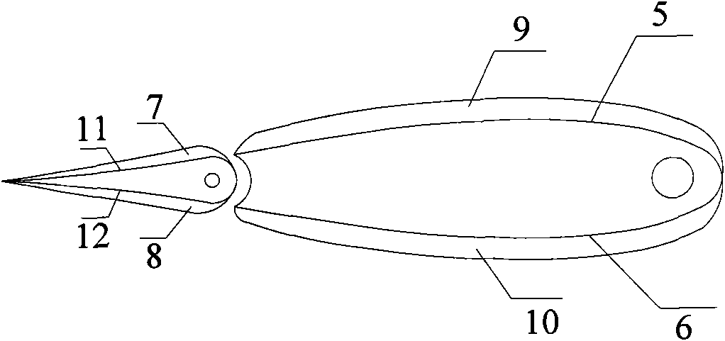
[0016] combine figure 1 and figure 2 . The structure is a flap stabilizer fin of a ship, which is similar to an airfoil with flaps. The fin axis z1 and the flap fin axis z2 are connected to the hull of the ship, and the free ends of the upper fin surface 1 and the lower fin surface 2 are respectively 5 and 6, the free ends of the upper fin surface 3 and the lower fin surface 4 of the flap are respectively 7 and 8, and baffle plates 9, 10, 11, 12 (10 and 12 in figure 2 marked in). The baffles include an upper fin baffle 9 , a lower fin baffle 10 , an upper flap fin baffle 11 and a lower flap fin baffle 12 .

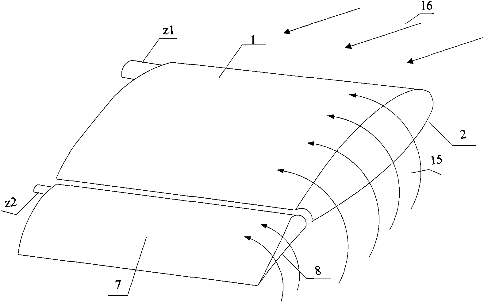
[0017] combine image 3 , Figure 4 and Figure 5 The generation of the wing tip vortex of the flap stabilizer and the principle of weakening the wing tip vortex of the present invention are further described.

[0018] Such as image 3 As shown, th...


PUM


Abstract

The invention provides a drag-reducing device of a anti-rolling fin of a ship wing flap, comprising a fin and a wing flap, wherein one end of the fin is provided with a fin shaft; one end of the wing flap is provided with a wing flap fin shaft; the fin shaft and the wing flap fin shaft are connected with a ship hull; the upper fin surface at the free end of the fin is provided with an upper fin surface baffle, and the lower fin surface at the free end of the fin is provided with a lower fin surface baffle; the upper wing flap fin surface at the free end of the wing flap is provided with an upper wing flap fin surface baffle, and the lower wing flap fin surface at the free end of the wing flap is provided with a lower wing flap fin surface baffle. The invention has simple structure and easy installation and realization and can effectively reduce the induced resistance of a fin stabilizer, enhance the lift efficiency of the anti-rolling fin of the wing flap, prevent a water flow medium cavitation phenomenon from generation and enhance the anti-rolling effect of the anti-rolling fin of the wing flap and the safety and the economy of ship navigation.

Description

technical field [0001] The invention relates to a ship anti-rolling device, in particular to a flap-stabilizing fin drag-reducing device. Background technique [0002] Among the ship anti-rolling devices, the fin stabilizer is a kind of anti-rolling device that effectively provides lift. The fin stabilizer is an airfoil-type control airfoil. Due to the existence of the wingtip, when the ship is running, the upper and lower fin surfaces of the stabilizer fin have a certain pressure due to the difference in water flow velocity. If it is poor, the water flow will turn from the high pressure side to the low pressure side at the free end, and the water flow near the fin tip will be twisted due to backward flow and upward flow to form a wingtip vortex. The rotation of the wingtip vortex produces upwash and downwash water flow, which changes the lift force of the fin stabilizer and induces drag. The higher the speed of the vortex, the generated low pressure may reach the cavitati...

Claims


Application Information

Patent Timeline
Patent Type & Authority Applications(China)
IPC IPC(8): B63B39/06
Inventor 刘胜常绪成李冰李高云王宇超
Owner HARBIN ENG UNIV
Why Eureka
Try Eureka