Blade tip winglet, wind turbine blade and blade synergy calculation method

A technology for wind turbine blades and main blades, which is applied in the field of wind turbine blade and blade efficiency calculation, and blade tip winglet, can solve the problem of inability to effectively guide the simulation calculation of blade tip winglet, unable to provide better implementation inspiration, and increase efficiency. The principle is not explained, etc., to achieve the effect of improving lift, increasing power coefficient, and reducing induced resistance

Active Publication Date: 2020-08-18
北京博比风电科技有限公司
View PDF8 Cites 3 Cited by
  • Summary
  • Abstract
  • Description
  • Claims
  • Application Information

AI Technical Summary

Problems solved by technology

However, the limited range of each parameter does not correspond to the description of the synergistic result, and the synergistic principle is not explained, which cannot provide better implementation inspiration
And for the tiplet structure, which includes fewer parameters, it cannot effectively guide the simulation calculation of the tiplet

Method used


Image

  • Blade tip winglet, wind turbine blade and blade synergy calculation method
  • Blade tip winglet, wind turbine blade and blade synergy calculation method
  • Blade tip winglet, wind turbine blade and blade synergy calculation method

Examples


Embodiment 1

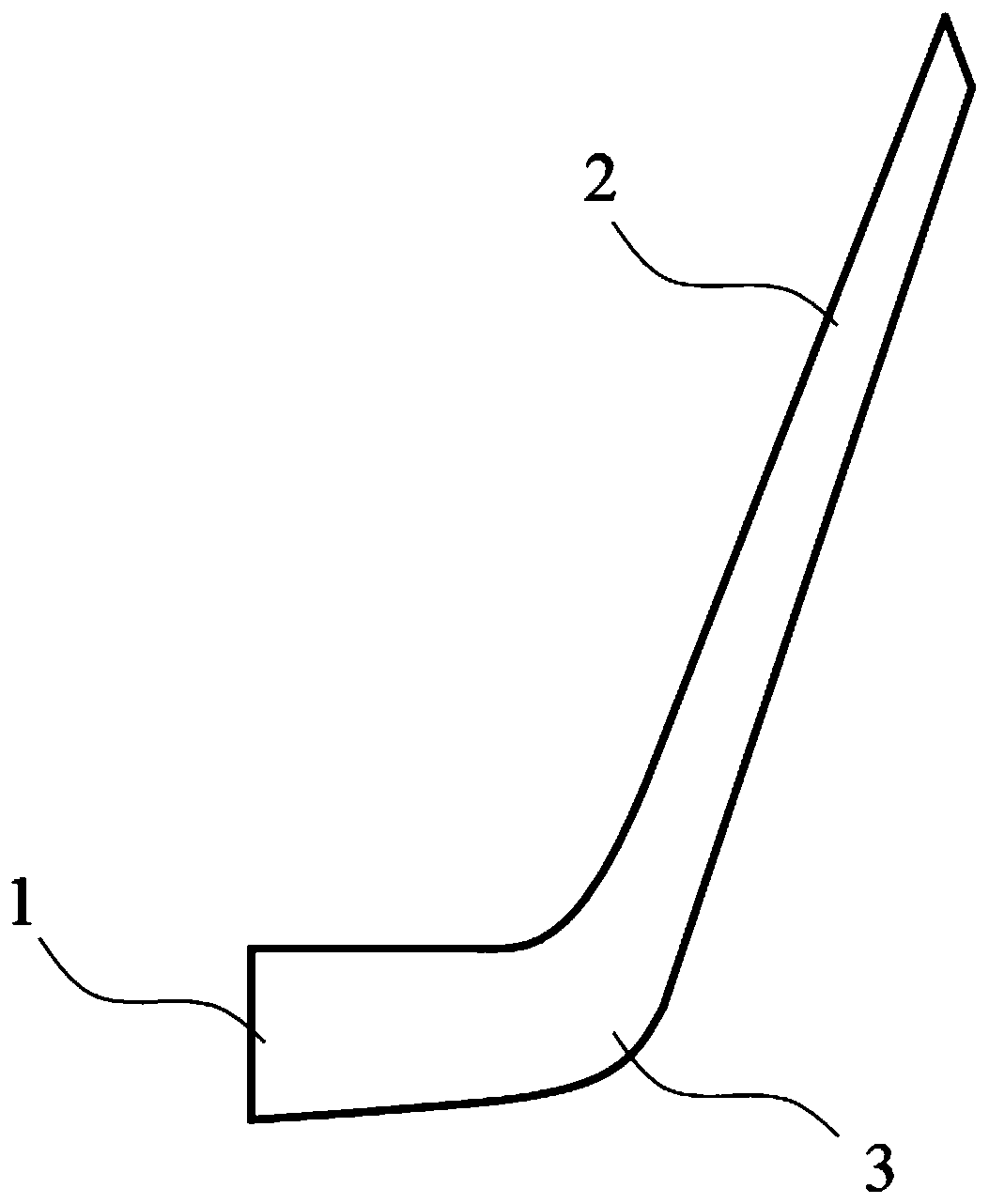
[0073] This embodiment specifically discloses a blade tip winglet, which is arranged at the end of the wind turbine blade to increase the power coefficient by reducing the induced resistance of the wind turbine blade, including the connecting section 1 and the blade tip section 2, and also includes a smooth transition The arc section 3 connecting the connecting section 1 and the blade tip section 2; the windward side of the blade tip section 2 forms a swept wing structure; the parameters of the blade tip section 2 are defined, and the parameters include: installation angle , height, inclination angle, torsion angle, and sweep angle; the parameters also include the starting position L of the leading edge, and the starting position L is between the windward leading edge of the connecting segment 1 and the front end of the bottom of the tip segment 2 setting the starting position L between 0 and 0.20c increases the power coefficient of the tiplet and the attached wind turbine blad...

Embodiment 2

[0075] This embodiment specifically discloses a blade tip winglet, which is arranged at the end of the wind turbine blade to increase the power coefficient by reducing the induced resistance of the wind turbine blade, including the connecting section 1 and the blade tip section 2, and also includes a smooth transition The arc section 3 connecting the connecting section 1 and the blade tip section 2; the windward side of the blade tip section 2 forms a swept wing structure; the parameters of the blade tip section 2 are defined, and the parameters include: installation angle , height, inclination angle, torsion angle, and sweep angle; the parameters also include the starting position L of the leading edge, and the starting position L is between the windward leading edge of the connecting segment 1 and the front end of the bottom of the tip segment 2 setting the starting position L between 0 and 0.20c increases the power coefficient of the tiplet and the attached wind turbine blad...

Embodiment 3

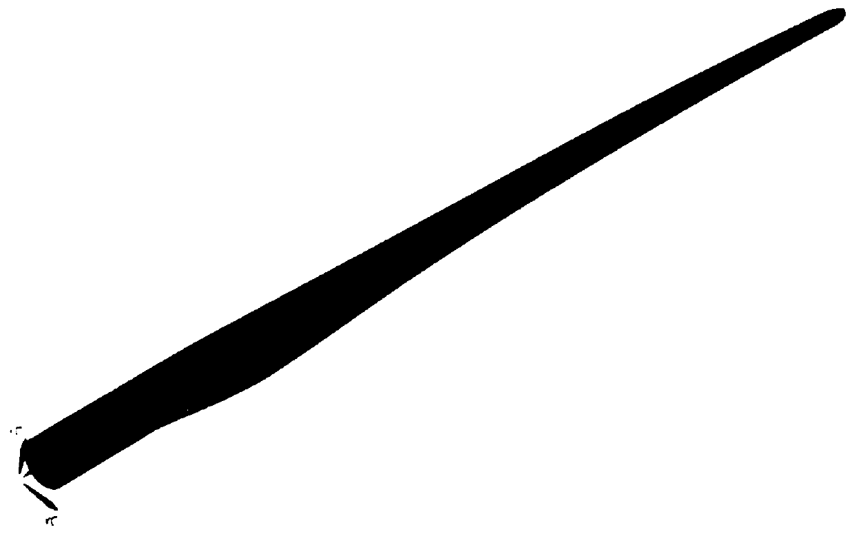
[0079] This embodiment specifically discloses a wind turbine blade, such as figure 1 and Figure 18 As shown, it includes a main blade assembled on a horizontal axis generator set, and a tiplet is provided at the end of the main blade.

[0080] The tiplet includes a connecting section 1 and a tip section 2, and also includes an arc section 3 for smooth transition connecting the connecting section 1 and the tip section 2; the windward side of the tip section 2 forms a swept wing structure ; The parameters of the blade tip section 2 are defined, and the parameters include: installation angle, height, inclination angle, torsion angle and sweep angle; the starting position L of the leading edge is also included in the parameters, and the starting position The starting position L is the distance between the windward leading edge of the connecting section 1 and the front end of the bottom of the tip section 2.

[0081] The parameters of the tip section 2 include:

[0082] The sta...


PUM


Abstract

The invention belongs to the field of wind power generation, and discloses a blade tip winglet, a wind turbine blade and a blade synergy calculation method. The blade tip winglet is arranged at the end part of the wind turbine blade and is used for increasing a power coefficient by reducing induced drag of the wind turbine blade. The blade tip winglet comprises a connecting section and a blade tipsection, and further comprises an arc-shaped section used for smoothly connecting the connecting section with the blade tip section in a transition mode, wherein a sweepback wing structure is formedon the windward side of the blade tip section; parameters of the blade tip section are defined, wherein the parameters comprise a mounting angle, height, an inclination angle, a torsion angle and a sweepback angle; the parameters further comprise an initial position L of the leading edge, and the initial position L is a distance value between the windward leading edge of the connecting section andthe most front end of the bottom of the blade tip section; and the initial position L is set between 0 and 0.20<c> to increase the power coefficient of the blade tip winglet and the connected wind turbine blade. According to the blade tip winglet, the wind turbine blade and the blade synergy calculation method, by defining multiple parameter sizes, the induced drag is integrally reduced, so thatthe lift force is improved, and the power coefficient is increased.

Description

technical field [0001] The invention belongs to the technical field of wind power generation equipment, and in particular relates to a tiplet winglet, a wind turbine blade and a blade efficiency calculation method thereof. Background technique [0002] The wind energy output of modern large-scale horizontal axis wind turbines is greatly affected by the incoming wind conditions. In the non-design point state, the power output and wind energy utilization efficiency will be significantly reduced. On the one hand, when the blades of the wind turbine with large aspect ratio rotate, due to the pressure difference between the pressure surface and the suction surface of the blade tip, the high-pressure fluid bypasses the blade tip to form a complex three-dimensional flow, generating a high-intensity blade tip vortex. Under the action of the field, the helically developed tip vortex will have a relatively strong induction effect on the blade, resulting in a decrease in blade efficien...

Claims


Application Information

Patent Timeline
Patent Type & Authority Applications(China)
IPC IPC(8): F03D1/06F03D17/00G06F30/17G06F30/20G06F113/06G06F111/10
CPCF03D1/0633F03D1/0675F05B2240/221F05B2240/30F03D17/00G06F30/17G06F30/20G06F2111/10G06F2113/06Y02E10/72
Inventor 李荣
Owner 北京博比风电科技有限公司
Why Eureka
Try Eureka