
Non-return device for flow regulation

A technology of flow regulation and non-return, which is applied in the field of sanitary ware, can solve the problems of complex structure of flow regulation non-return valve and insufficient response sensitivity, and achieve the effect of enhancing market competitiveness, product sensitivity, and effectively adjusting flow and non-return

Inactive Publication Date: 2010-11-10
XIAMEN SOLEX HIGH TECH IND CO LTD +1
View PDF6 Cites 6 Cited by
  • Summary
  • Abstract
  • Description
  • Claims
  • Application Information

AI Technical Summary

Problems solved by technology

[0003] The present invention provides a flow regulating non-return device, which solves the shortcomings of the flow regulating non-return valve in the background technology, which have complicated structure and insufficient response.

Method used


Image

  • Non-return device for flow regulation
  • Non-return device for flow regulation
  • Non-return device for flow regulation

Examples


Embodiment Construction

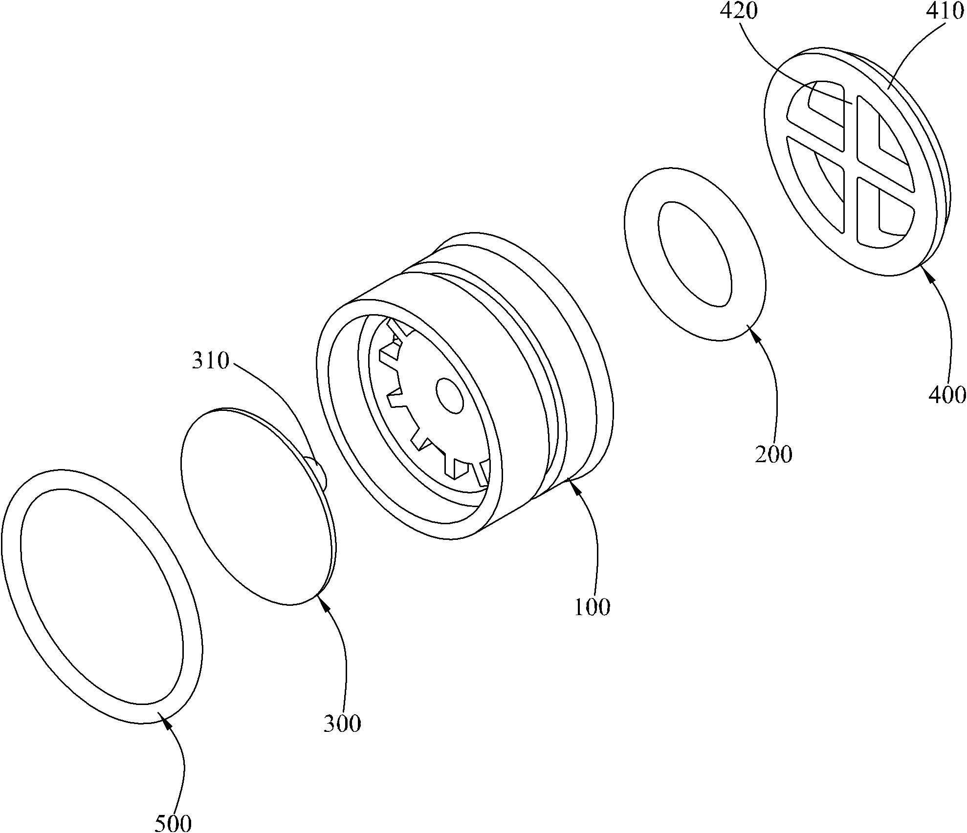
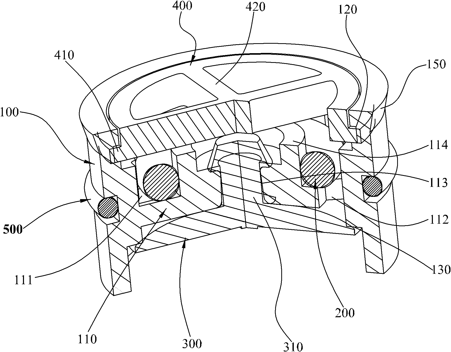
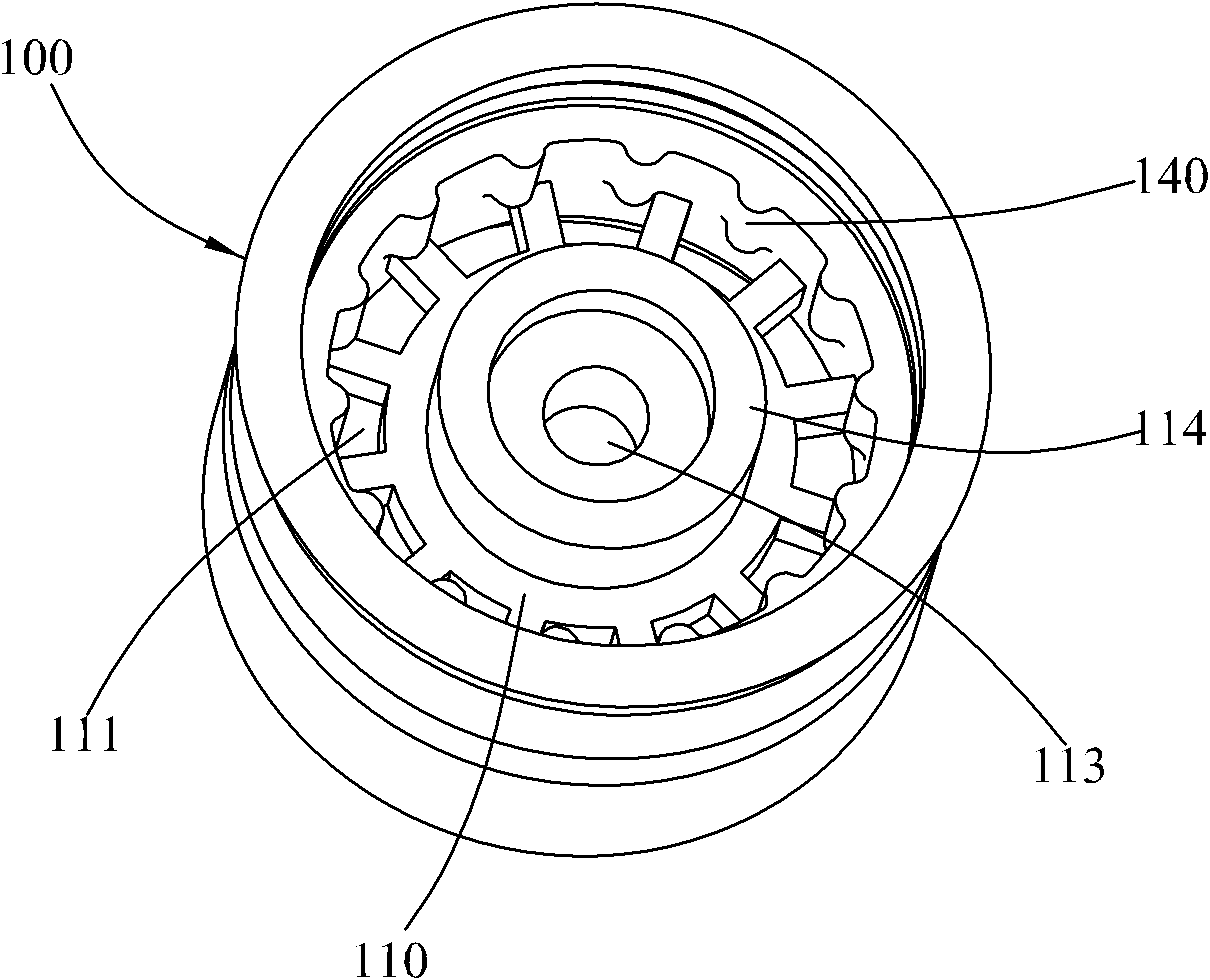
[0035] see Figure 1 to Figure 7 , which shows the flow regulating non-return device provided by the first embodiment of the present invention.

[0036] Such as figure 1 As shown, the flow regulating non-return device includes a body 100, a flow regulating member 200, a non-return sheet 300, an upper cover 400 and a sealing member 500, wherein: the flow regulating member 200 and the non-return sheet 300 are separately arranged on both sides of the body 100, the anti-reverse piece 300 has a raised central axis 310 to be fixedly connected to the body 100, the upper cover 400 is set on the body 100, the The sealing element 500 is sleeved outside the body 100 .

[0037] Such as figure 2 As shown, the body 100 has a water inlet connected to a water source, and a water outlet, in which a support seat 110 is fixed, and an attachment groove 111 is formed between the support seat 110 and the body 100. A protruding shaft 114 is provided at the center of the groove surface, an attac...


PUM


Abstract

The invention discloses a non-return device for flow regulation, which comprises a water inlet end, a water outlet end and a body communicated with a water source, wherein a supporting seat is arranged in the body and comprises a mounting and collecting groove, a through hole is formed on the groove surface of the mounting and collecting groove, and a mounting and connecting hole is formed at the center of the groove surface; and the non-return device further comprises a flow regulating part and a non-return sheet, wherein the flow regulating part is positioned in the mounting and collecting groove and positioned on the through hole, and can produce the elastic deformation under the action of water pressure for changing the flow area of the through hole; and a central shaft which adapts to the mounting and connecting hole is convexly arranged at the center of the non-return sheet, and can be affected by the water pressure for sealing the through hole or communicating the through hole with the water outlet end. The non-return device for flow regulation is suitable for automatic assembly, can improve the production efficiency and further has the advantages of compact structure and high sensitivity.

Description

technical field [0001] The invention relates to the field of sanitary ware, in particular to a flow regulating non-return device installed in a pipeline. Background technique [0002] Chinese Patent No. CN200920137849.8, a utility model titled "Flow Adjustment Check Valve", which includes a sleeve, a flow limiting device and a one-way valve. The one-way valve is sealed at the water outlet end of the sleeve, which includes A valve body, a spool, a spring and a bonnet. Although the flow regulating check valve realizes the functions of flow limitation and check, it has the following disadvantages: 1. The check valve for check needs to be combined with a spring 2. When the one-way valve is opened, it must overcome the elastic force of the spring and the friction between the valve body and the inner wall of the sleeve, and when the one-way valve is reset, it must overcome the gravity of the valve core And the friction between the valve body and the inner wall of the sleeve, so t...

Claims


Application Information

Patent Timeline
IPC IPC(8): F16K17/34F16K15/14
CPCG05D7/012
Inventor 刘梓光陈添育黄祥周华松
Owner XIAMEN SOLEX HIGH TECH IND CO LTD
Learn More