Aerosol inhaling system

An aerosol and aspirator technology, applied in the direction of inhalers, spray devices, nebulizers for treatment, etc., can solve the problems of loss of solution, aerosol response delay, etc., to prevent waste loss, shorten response time, and easy suction Effect

Active Publication Date: 2010-11-10
JAPAN TOBACCO INC
View PDF0 Cites 13 Cited by
  • Summary
  • Abstract
  • Description
  • Claims
  • Application Information

AI Technical Summary

Problems solved by technology

Such self-spraying of steam will not only cause the solution to be lost in vain, but also cause the front end of the tube to become empty in many cases just before the user starts the suction action.
Therefore, for example, even if the supply pump is operated in conjunction with the suction action of the user, since the front end of the tube is filled with the solution again, and it takes time for the vapor of the solution to spray out from the front end of the tube by itself, the time from the suction action of the user to the Aerosol-generating responses also create delays

Method used


Image

  • Aerosol inhaling system
  • Aerosol inhaling system
  • Aerosol inhaling system

Examples


Embodiment Construction

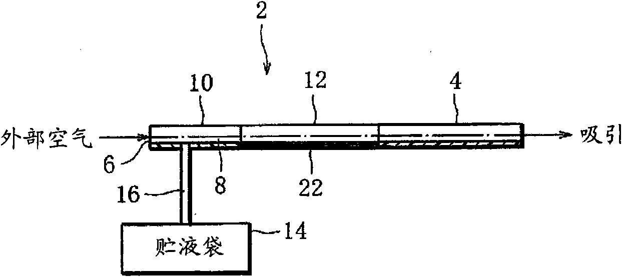
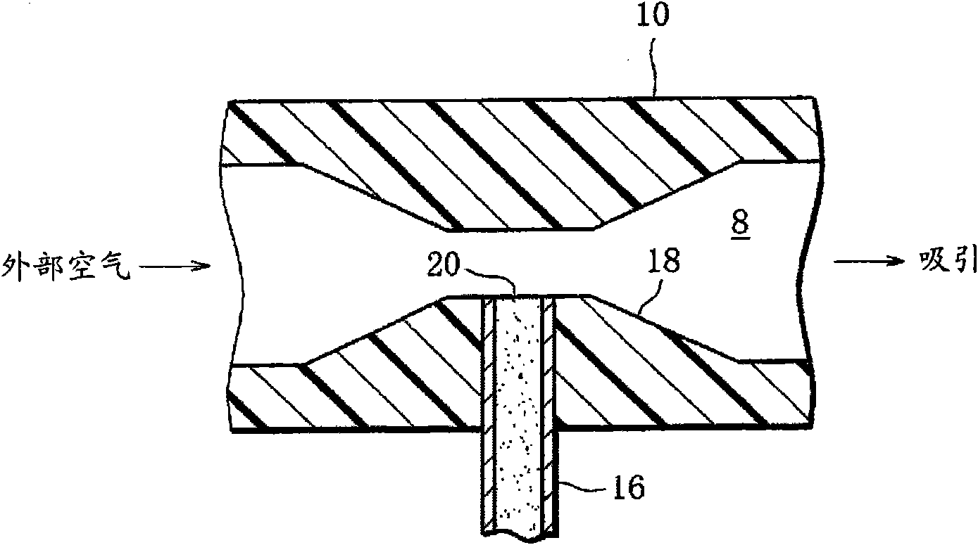
[0040] figure 1 and figure 2 The aerosol suction system (hereinafter simply referred to as the system) of the first embodiment is shown.

[0041] The system includes an aspirator 2 which has a rod shape as a whole. The aspirator 2 has a front end portion, a middle portion, and a rear end portion, and the rear end portion is formed as a nozzle opening 4 . The aspirator 2 has an external air inlet 6 at its front end, and the front end and the middle portion define an aerosol generating flow path 8 extending from the external air inlet 6 to the mouthpiece 4 .

[0042]More specifically, the front end and the middle portion of the aspirator 2 are respectively formed by an air introduction pipe 10 provided with an external air introduction port 6 and a tubular electric heater 12 which is a tubular heating element. The passage is formed as an aerosol generating channel 8 .

[0043] On the other hand, a flexible liquid storage bag 14 is prepared outside the aspirator 2, and the l...


PUM


Abstract

An aerosol inhaling system includes an inhaler (2) having in it an aerosol generation flow path (8) for interconnecting an outside air introduction opening (6) and a mouth piece (4), with a part of the aerosol generation flow path (8) constructed from a tubular electric heater (12); a flexible storage bag (14) prepared separately from the inhaler (2) and having stored in it solution as a raw material for aerosol; and a narrow supply tube (16) for interconnecting the liquid storage bag (14) and the inhaler (2). The narrow supply tube (16) has a supply opening (20) open in the aerosol generation flow path (8) and located on the upstream of the heater (12). In user's inhaling operation, solution in the narrow supply tube (16) is drawn out of the supply opening (20) into the aerosol generation flow path (8). When the drawn out solution is transferred to the heater (12) together with inhaled air flow flowing toward the mouth piece (4), the solution is heated and evaporated by the heater (12) to generate aerosol in the inhaled air flow.

Description

technical field [0001] The present invention relates to an aerosol suction system for supplying medicine, luxury goods, etc. to a user in the form of aerosol. Background technique [0002] Such an aerosol suction system is disclosed in, for example, Japanese Patent Application Laid-Open No. 2000-510763. The system of this publication includes a supply pump for supplying a solution (liquid substance) as a raw material of an aerosol, and the supply pump is connected to a tube. The tube has an open front end, and the inside of the tube is filled with the solution supplied from the supply pump. In addition, an electric heater is arranged at the tip of the tube so as to be adjacent to the mouth of the suction nozzle and to surround the tip of the tube. The electric heater heats the solution located in the front end of the tube to evaporate it, and the vapor of the solution is ejected from the front end of the tube by itself. Such solution vapor contacts the air sucked by the u...

Claims


Application Information

Patent Timeline
Patent Type & Authority Applications(China)
IPC IPC(8): A61M11/00A61M15/00B05B7/16
CPCA61M11/041A61M11/042
Inventor 山田学片山和彦佐佐木宏
Owner JAPAN TOBACCO INC
Why Eureka
Try Eureka