Table-top cutter

A desktop cutting machine and rotary table technology, applied in sawing equipment, metal sawing equipment, sawing machine devices, etc., can solve the problems of increasing wall thickness, large supporting span, inability to accurately position, and reduce space. , to ensure the support rigidity, reduce the effect of deflection

Inactive Publication Date: 2010-11-17
MAKITA CORP
View PDF1 Cites 1 Cited by
  • Summary
  • Abstract
  • Description
  • Claims
  • Application Information

AI Technical Summary

Problems solved by technology

The above-mentioned existing limit stopper has the following structure, that is, the limit stopper is fixed on both sides of the base located on the left and right sides of the rotary table, and is held in a suspended state above the rotation center of the rotary table. Therefore, the larger the size of the rotary table (enlargement), the larger the support span of the overhead part of the limit stopper, as a result, in order to ensure that the limit stopper has sufficient rigidity, it is necessary to increase the Larger size of the limit stop (increased wall thickness)
If the limit stopper cannot be ensured to have sufficient rigidity, the center of the overhead part of the limit stopper will be subjected to the rotational torque (cutting force) of the rotating tool transmitted through the material to be cut, in order to limit the position of the material to be cut Due to the impact of the user against the material to be cut or other objects, the limit stopper will be deflected in the plane direction of the worktable, and in serious cases, it will be deformed and the problem of inaccurate positioning will occur.

Method used


Image

  • Table-top cutter
  • Table-top cutter
  • Table-top cutter

Examples


Embodiment Construction

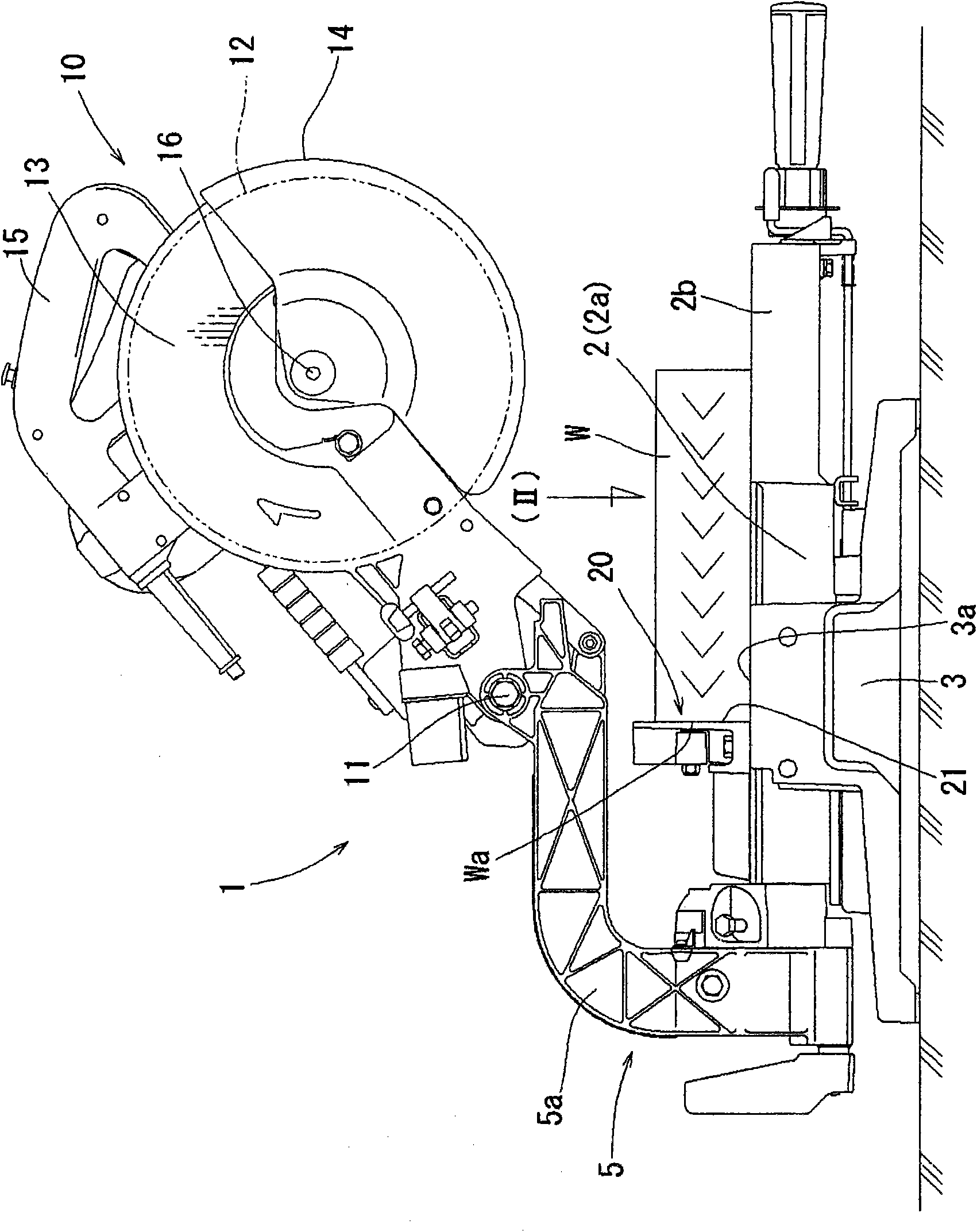
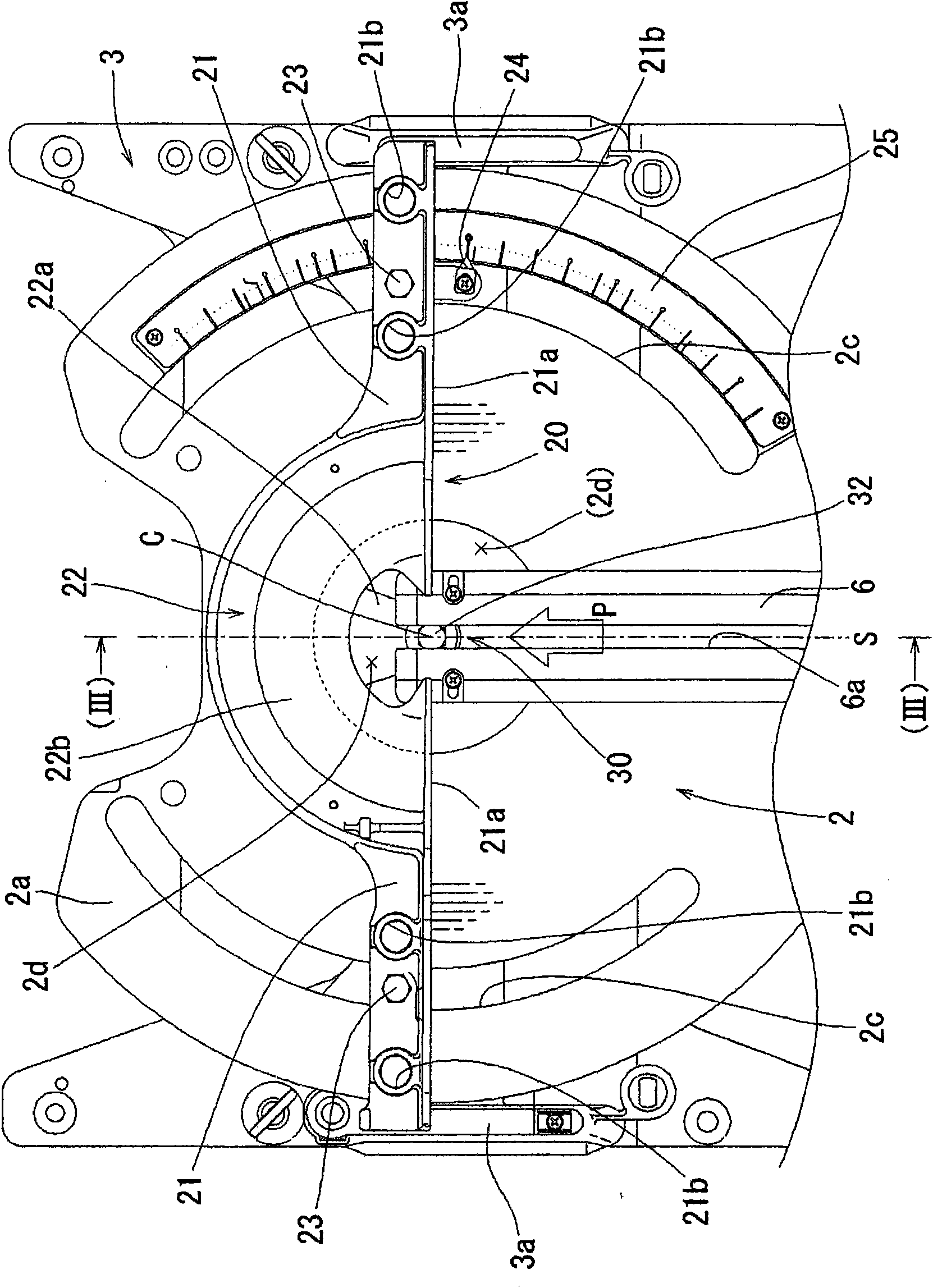
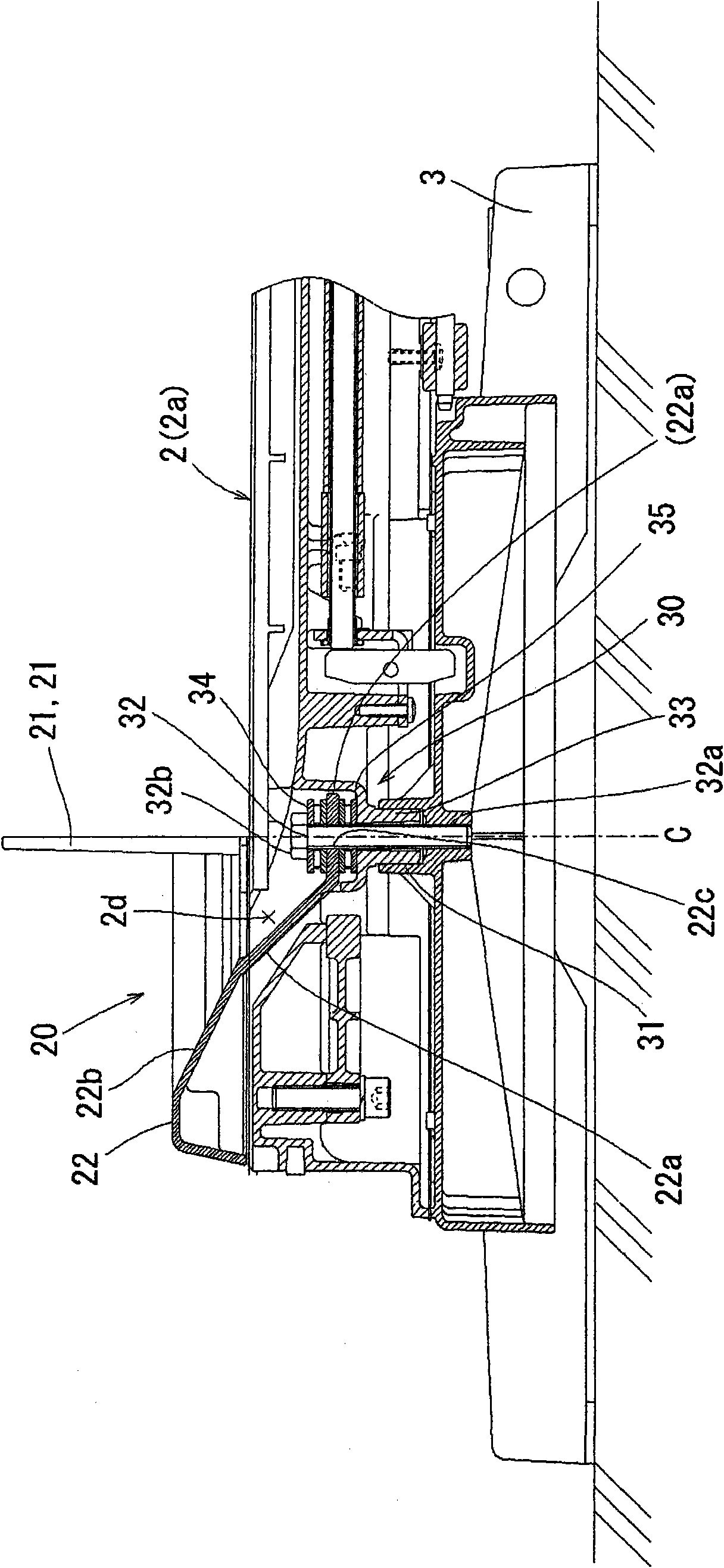
[0035] The following is based on Figure 1-Figure 12 Embodiments of the present invention will be described. figure 1 The whole table cutting machine 1 provided with the stopper 20 of this embodiment is shown. The desktop cutting machine 1 of this embodiment is characterized by the supporting structure of the limit stopper 20, which is used to position the position of the material W to be cut on the rotary table 2, and serves as the other part of the cutting machine. The basic structure and the like are the same as those of the prior art, and there is no need to change this part in this embodiment, so detailed description thereof will be omitted.

[0036] The desktop cutting machine 1 has: a rotary table 2 for resting the material W to be cut on the upper surface; a base 3 supporting the rotary table 2 in a manner that the rotary table 2 can rotate in a horizontal plane; Cutting machine body 10, at the rear portion of rotary table 2 ( figure 1 The middle left part) is provi...


PUM


Abstract

A table-top cutter having a rotation table supported by a base in a horizontally rotatable manner and also having a fence for positioning a material to be cut, the fence being supported at opposite ends thereof by the base so as to radially straddle over the rotation table. The positioning fence has increased supporting rigidity to eliminate deflection of the fence at the center thereof, and this solves problems of conventional products in which the center of the fence is prone to deflect due to the fence being supported only at opposite ends thereof in order to allow rotation of the rotation table. A center support section (22a) is provided at the center of the span of the positioning fence (20). The center support section (22a) is extended to the lower surface of the rotation table (2) through a center recess (2d) of the table and connected to a rotation support section (30) of the base (3).As a result, supporting rigidity of the positioning fence (20) particularly at the center thereof is increased.

Description

technical field [0001] The invention relates to a desktop cutting machine, which has the following working mode, that is, the cutting machine body equipped with a circular saw blade and other rotary cutters is moved downwards, so that the cut material fixed on the workbench Carry out cutting. [0002] In this specification, the cutting process includes not only the process of separating the work material, but also the grooving process of cutting the work material without separating it, and the process of grinding the work material. processing etc. Background technique [0003] This desktop cutting machine has a workbench and a cutting machine body, the workbench is used to rest the material to be cut on its upper surface, and the cutting machine body can be moved up or down relative to the workbench. As for the workbench, the structural form of a rotating workbench can be adopted, and the rotating workbench is supported on a base and can rotate in a horizontal plane. When...

Claims


Application Information

Patent Timeline
Patent Type & Authority Applications(China)
IPC IPC(8): B23D47/02B23D45/14B27B5/29
CPCB23D47/025B27B5/29B23D45/062
Inventor 小岛真也山村刚
Owner MAKITA CORP
Why Eureka
Try Eureka