Supercharge Your Innovation With Domain-Expert AI Agents!

A beam for a heavy vehicle

A technology for heavy-duty vehicles and frames, applied in the field of heavy-duty vehicles, can solve problems such as increased manufacturing costs and increased component weights

Inactive Publication Date: 2010-11-17
VOLVO LASTVAGNAR AB
View PDF0 Cites 8 Cited by
  • Summary
  • Abstract
  • Description
  • Claims
  • Application Information

AI Technical Summary

Problems solved by technology

However, such a multi-layer design will result in increased manufacturing costs and increased component weight

Method used


Image

  • A beam for a heavy vehicle
  • A beam for a heavy vehicle
  • A beam for a heavy vehicle

Examples


Embodiment Construction

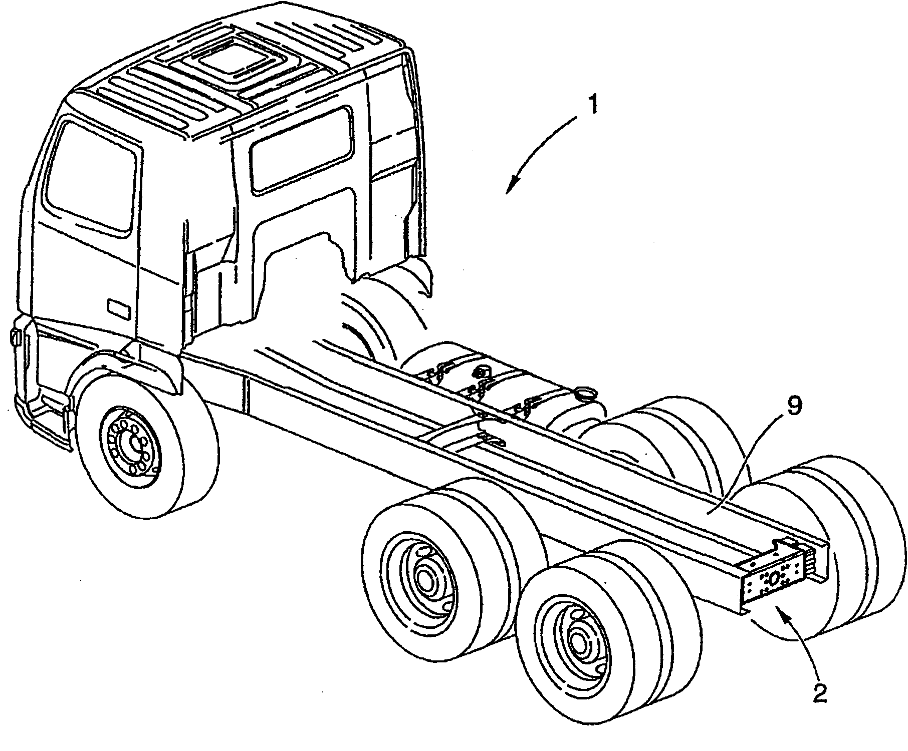
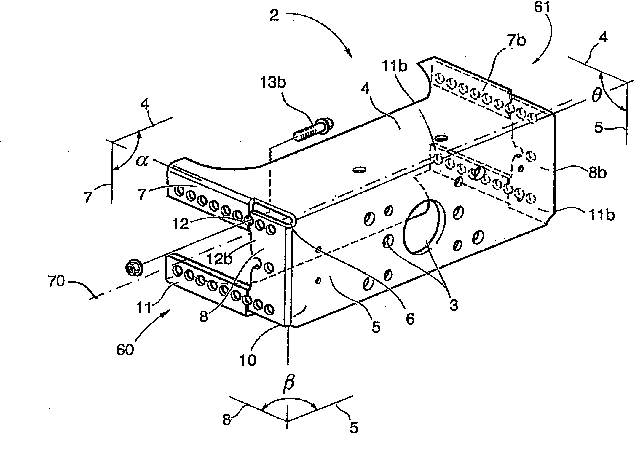
[0021] figure 1 It is a perspective view of a heavy vehicle 1 provided with a beam 2 according to the invention. The heavy vehicle is a truck, and the beam is the end cross beam used to tow the trailer. The end crossbeam formed as a U-shaped beam may have holes 3 (see figure 2 ) And / or any other device used to mount a coupling device (not shown) to the end cross beam. The coupling device is used to achieve the connection to the trailer to be towed by the truck. The end cross beam is arranged between and attached to the two longitudinal main beams of the frame 9 of the truck at the rear of the truck 1.

[0022] As from figure 2 It can be seen that the beam 2 includes a first part 4 and a second part 5 that are connected to each other and are angled with respect to each other to form a corner 6. At the first end 60 of the beam, the first part 4 has a flange 7 extending downward in a geometric plane, and the second part 5 has a flange 8 extending forward and arranged substantial...


PUM


Abstract

The invention relates to a beam (2) for a heavy vehicle (1). The beam comprises a first portion (4) and a second portion (5) which are connected to each other and angled relative each other so as to form a corner (6). The first portion (4) has a flange (7) with a main extension in a geometric plane, and the second portion (5) has a flange (8) with a main extension substantially in the same geometric plane. At least a part of the periphery portion (12) of the first portion flange (7) and at least a part of the periphery portion (12b) of the second portion flange (8) are connected to each other by means of a connecting member (13; 13b) acting on both the first portion flange (7) and the second portion flange (8).

Description

Technical field [0001] The invention relates to a beam for heavy vehicles according to the preamble of claim 1. [0002] The present invention can be applied to heavy vehicles, especially trucks. However, the present invention is not limited to trucks, but can also be used for, for example, wheel loaders, dump trucks, excavators, and buses. Background technique [0003] In a heavy vehicle having a traction member for connection to a towed trailer, the traction member is arranged to distribute the load from the towed trailer to the frame of the heavy vehicle. It is important that the load does not cause stress concentration in the frame to ensure that the chassis can withstand the load and avoid the propagation of cracks. [0004] A traction member consisting of an end cross beam arranged at the rear of the traction vehicle is generally shaped as a U-shaped beam, which is attached to the longitudinal main beam of the chassis frame. In addition to the portion forming the U-shaped en...

Claims


Application Information

Patent Timeline
Patent Type & Authority Applications(China)
IPC IPC(8): B62D21/02B60D1/14B62D25/20
CPCB60D1/485B62D21/02
Inventor 延斯·古斯塔夫松马蒂亚斯·贝里隆德
Owner VOLVO LASTVAGNAR AB
Features
  • R&D
  • Intellectual Property
  • Life Sciences
  • Materials
  • Tech Scout
  • Unparalleled Data Quality
  • Higher Quality Content
  • 60% Fewer Hallucinations
Learn More