Conical swirling flow vertical shaft
A swirl shaft and conical technology, which is applied in the field of swirl shafts with high water head and large flow rate, can solve the problems of increased cavitation and cavitation on the wall surface, difficulty in aeration, and high flow rate, so as to increase the resistance of water flow along the process and improve the energy dissipation rate , the effect of improving efficiency
- Summary
- Abstract
- Description
- Claims
- Application Information
AI Technical Summary
Problems solved by technology
Method used
Image
Examples
Embodiment 1
[0027] The conical swirl shaft in this embodiment is designed according to the spillway tunnel of a hydropower station project. In the case of checking the flood, the design discharge volume of the spillway tunnel is 272.61m 3 / s, the top elevation is 2797m, at 2765m it starts to shrink to join the conical shaft section, and the elevation of the bottom plate of the shaft spillway is 2690m.
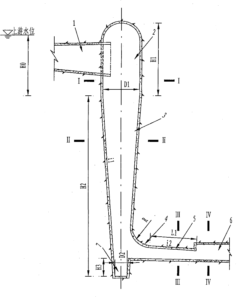
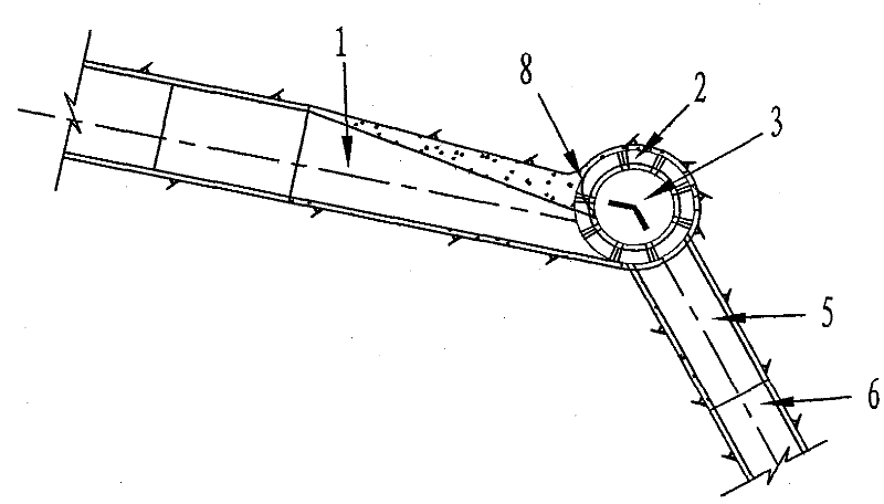
[0028] In this embodiment, the structure of the conical swirl shaft is as follows figure 1 , Figure 4 As shown, it includes a vortex chamber section 2 and a vertical shaft section 3 connected to the vortex chamber section; the vortex chamber section 2 is provided with a water inlet for tangentially introducing the water flow in the channel 1 into the vortex chamber, and the vertical shaft section 3 is a conical cylinder with a large top and a small bottom. The vortex chamber section 2 is connected with the diversion channel 1, and its connecting position is to make the water flow in the...
Embodiment 2
[0032] The conical stepped swirl shaft in this embodiment is designed according to the flood discharge tunnel of a hydropower station project, and the maximum discharge flow is 1245m 3 / s, the elevation of the top of the shaft spillway tunnel is 1993m, and at 1953m it begins to shrink to the conical stepped shaft section, and the elevation of the bottom plate of the shaft spillway tunnel is 1778m.
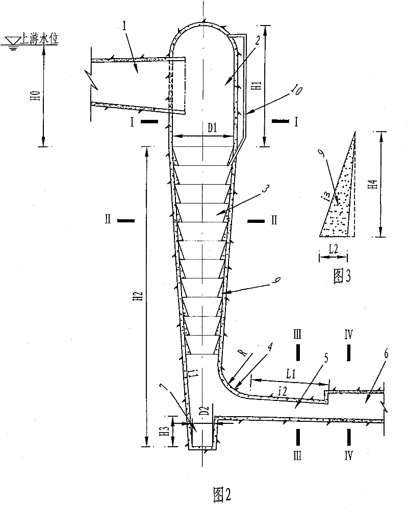
[0033] In this embodiment, the structure of the conical step swirl shaft is as follows figure 2 , Figure 4 As shown, it includes a vortex chamber section 2 and a vertical shaft section 3 connected to the vortex chamber section; the vortex chamber section 2 is provided with a water inlet for tangentially introducing the water flow in the channel 1 into the vortex chamber; the vertical shaft section 3 is a conical cylinder with a large upper part and a smaller lower part, and a stepped energy dissipator 9 is arranged on the well wall (the stepped energy dissipater 9 starts at the ...
PUM
 Abstract
Description
Claims
Application Information
 - R&D
- Intellectual Property
- Life Sciences
- Materials
- Tech Scout
- Unparalleled Data Quality
- Higher Quality Content
- 60% Fewer Hallucinations
Browse by: Latest US Patents, China's latest patents, Technical Efficacy Thesaurus, Application Domain, Technology Topic, Popular Technical Reports.
© 2025 PatSnap. All rights reserved.Legal|Privacy policy|Modern Slavery Act Transparency Statement|Sitemap|About US| Contact US: help@patsnap.com


